|
Posted: 2/10/2016 5:25:18 PM EDT
[Last Edit: AFCarbon15]
I got into 80%'ers a little over two years ago. I had absolutely zero experience when I started. Since then I've studied a lot of specs and different methods (all on a mini-mill) I have found a few variations which after fighting my way through the troubles and headaches, I thought I'd share my current methods and documents
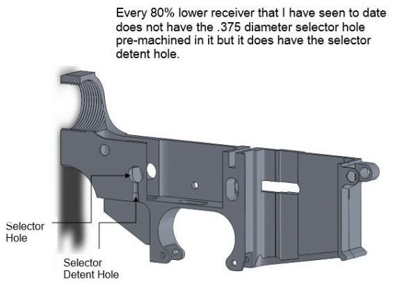
Also, since we don't currently have a dedicated 80% sub-forum, or a tacked info thread. Maybe others can add good info to help new guys jump into the game with a little more confidence. Usually these threads start well but quickly go downhill with legal interpretations. Maybe we can have a separate thread for the legal discussions. Being this is a technical forum, I'll keep my comments to the technical aspects, methods/techniques, specs and tooling primarily. Also, most of this I don't expect would be much help if you are using any of the router/jig methods Here's some data I've comprised that helps me through the process. This is by no means the end all be all of the process. I am no machinist. Mostly it just works for me. This is my tool path for the FCG pocket. It is a slight variation of one I found somewhere online. The front take down pin is X zero, to locate, if I don't use a jig, I just put a 1/4" pin or drill bit in the hole and locate each side to calculate center. I usually use a jig though, which I drilled a hole at center of the pin off to the side so I can locate that hole. I'll post pictures later, it will make more sense. I center on the lower itself for Y, usually right in the middle of the FCG pocket area. The measurements are for the tool path of a 7/16 end mill. I've see variations for 3/8 and 1/4. But 7/16 seems to provide in the best radius. Perhaps others have more insight on other sizes. This is my cleaned up specs for the FCG holes. Again, for milling with DRO's using the front pivot pin hole as 0,0. When I use the mill, I only drill one side at a time, not all the way through both at once. I have found many slight variance for these numbers, but these seemed to be the most common and work for me. I'll post a start to finish video as soon as I get it edited and uploaded. My Method I start with a 3/8 roughing end mill. This takes a lot of the stress of the little mill. I follow the same path as the 7/16 EM, this gives me a built in .031 "oops" for the first 4 passes. First cut is in the back, if the rear lug is pre-cut or not. Just short of the 6.558 and 0 for Y. I then go counter clockwise around the pocket (climb mill) only around .020 deep for the first pass to get the layout. This is two-fold, I can double check everything to make sure my setup was correct and then I have an outline to follow so I can watch the milling instead of just staring at the DRO's the whole time. The first 6-8 I did, I was conventional milling, but I found the climb milling provides a better finish for the final pass so I just do that until the final pass. I mill about .300 in each of 4 passes. The first 2 go all the way around including the rear shelf, the last 2 only do the trigger/hammer/safety area. Usually my last pass, I go around .020 (x and y) over all the way around. That way I leave less work for my 7/16 EM which saves wear and tear on the one doing the finishing passes. Again, that's what works for me. I'm actually interested to see what other's experiences are. That's how we all learn. Here's a step by step I put together for the final pass. I have a step by step for the whole thing, I'll get that up soon. This is another modified spec of the side. It is mostly the way I found it, but I added a few and double checked as many as I needed. Which was quite a few while completing a 0% For AR308, I had to roll my own. I gathered specs until I got tired of the differences. I've only done two different brands, but they were different by a couple of thousandths. At least one spec sheet I found had a range instead of a solid number for the distance from the rear take-down pin to the safety. None of which were the same as the TM lower I had. So, to start, I locate off the safety detent for X zero, then locate the rear pin for Y zero, noting the X travel difference as I use that to drill the driver's side holes after locating the rear pin there. As I said, no formal machinist training, so what I do is all self taught. I do what works for me and what I think makes sense. Even if to a seasoned machinist I appear as a neanderthal just learning to swing a rock. This is my version of the side specs for drilling the FCG holes. (again my version, PLEASE comment if you don't understand or have a more preferred method.) This is the top view for milling the FCG pocket. 7/16" EM (as requested, I will notate that on the Image, eventually) Again, Y zero is based of locating each side and dividing by two. X zero for this one is the center of the bolt catch slot. I could probably use that for the AR15 as well, but it's more common to go by the pin, so I've stuck with it so far for the AR15. I'm not a fan of inconsistencies, but often the goes to simplification. [youtube]https://youtu.be/V7UY2Gw4rqM[/youtube] My 0% Project with lots of machine mods, tooling links and info. The Who Wants an 80% Forum Thread. Lots of tooling talk in here. Links to threads with lots of similar Q&A and related info: Jig Holding Questions External Link to Mini-mill Info General Beginner Advice from Machinists Home Model Engine Machinist Machine Mods Rysium X2 Mini-mill Mods I'll be adding more shortly... ETA: still adding... |
|
|
|
USA
|
[Last Edit: MemeWarfare]
[#1]
Outstanding, OP.
Your top-view drawing is the Holy-Grail first-timers need. I use transfer punches in jig plates to locate the 3 pin holes, but I use an identical DRO milling process for the FCG. Listen up 80% newbies, these are the droids you're looking for. ETA: OP, I would suggest you annotate your images with tool info so if someone saves the images they know what diameter end mill your measurements correspond to. Again, great job with this. You've done the community a service. |
|
|
|
[#2]
Originally Posted By airsix: Outstanding, OP. Your top-view drawing is the Holy-Grail first-timers need. I use transfer punches in jig plates to locate the 3 pin holes, but I use an identical DRO milling process for the FCG. Listen up 80% newbies, these are the droids you're looking for. ETA: OP, I would suggest you annotate your images with tool info so if someone saves the images they know what diameter end mill your measurements correspond to. Again, great job with this. You've done the community a service. Yeah all of this X2! And this needs to be pinned/stickied as well a kept from going into the Archives. If we ever get an 80% forums this for sure needs to be in there. |
|
|
|
IL, USA
|
[#3]
This looks great. I've never really even paid attention to 80% stuff and I can understand this.
The only question I'd have would be an accurate way of zeroing at a point that is in empty space. Would it be easier to have zeroed at a point where you could touch the side of the mill to a known point? |
|
|
TX, USA
|
[#4]
There needs to be something for 308 lowers too... there are no DPMS type blueprints available for the 308 lowers (all the ones out there are for Armalite).
I know the fire control area on the 308 lower is exactly the same as an AR15 but as to where to start it is a problem... I messed up a 80% 308 lower this way, and it's a more expensive mistake because 308 lowers are generally a lot more expensive than AR lowers (you can already buy AR 80% lowers from Tactical Machining for like 30 dollars) Amen to drilling one side at a time... It takes more time but you won't have the drill bit wandering off because of some freak occurrence. I do not have a DRO so I need to count off, but it's not too hard to do but you must keep track of your counts because if you do lose count for any reason, you have to start over. For the fire control hole I'm suggesting starting at the selector detent hole and working your way backwards. |
|
|
|
[Last Edit: AFCarbon15]
[#5]
Originally Posted By taiwanluthiers:
There needs to be something for 308 lowers too... there are no DPMS type blueprints available for the 308 lowers (all the ones out there are for Armalite). I know the fire control area on the 308 lower is exactly the same as an AR15 but as to where to start it is a problem... I messed up a 80% 308 lower this way, and it's a more expensive mistake because 308 lowers are generally a lot more expensive than AR lowers (you can already buy AR 80% lowers from Tactical Machining for like 30 dollars) Amen to drilling one side at a time... It takes more time but you won't have the drill bit wandering off because of some freak occurrence. I do not have a DRO so I need to count off, but it's not too hard to do but you must keep track of your counts because if you do lose count for any reason, you have to start over. For the fire control hole I'm suggesting starting at the selector detent hole and working your way backwards. I have those as well, AR308's. Rolled my own basically like the ones above as a collective of all the specs I've found scattered and what I've learned on my own. I have only done 6 or so AR308's so it might not be perfect, but they've all functioned without issue. I'll get those posted up soon. |
|
|
|
TX, USA
|
[Last Edit: taiwanluthiers]
[#6]
I did find one picture describing all the critical dimensions but I am not sure how correct they are. When I followed it it still seems to be off by at least .01".
Not sure why there are no blueprints for DPMS AR308's. How are those people making 80% AR308's getting their specs from? (or how they made the jig) 

|
|
|
USA
|
[#7]
Originally Posted By ZMan941:
This looks great. I've never really even paid attention to 80% stuff and I can understand this. The only question I'd have would be an accurate way of zeroing at a point that is in empty space. Would it be easier to have zeroed at a point where you could touch the side of the mill to a known point? Zeroing off the front pivot is the standard practice for the design. It is very simple to do. Your jig plate will have a 1/4" pin to measure off, or you can install a pin or even a drill shank in the pivot hole. Touch the edge of the pin, then move in .125" plus 1/2 the width of your edge-finding device and set your zero. |
|
|
GA, USA
|
[#8]
Can't wait for the video. Any way you can link the diagrams so they can be printed?
|
|
|
|
[#9]
Originally Posted By airsix:
Zeroing off the front pivot is the standard practice for the design. It is very simple to do. Your jig plate will have a 1/4" pin to measure off, or you can install a pin or even a drill shank in the pivot hole. Touch the edge of the pin, then move in .125" plus 1/2 the width of your edge-finding device and set your zero. Originally Posted By airsix:
Originally Posted By ZMan941:
Snip Zeroing off the front pivot is the standard practice for the design. It is very simple to do. Your jig plate will have a 1/4" pin to measure off, or you can install a pin or even a drill shank in the pivot hole. Touch the edge of the pin, then move in .125" plus 1/2 the width of your edge-finding device and set your zero. I have take it too far. I use an edge finder to locate one side of the pin, set that as zero, the locate the other side, divide by 2, move to that loc and reset zero. I don't have the fancy DRO with AVG functions. I then locate each side of the pin again, to see that each is the same distance. Double check and double check again. Since that sets the tolerance for everything I'm going to do from there on. I basically do the same for the Y axis, just using the sides of the lower rather than the pin. |
|
|
|
|
[Last Edit: RDTCU]
[#10]
Originally Posted By AFCarbon15:
I have take it too far. I use an edge finder to locate one side of the pin, set that as zero, the locate the other side, divide by 2, move to that loc and reset zero. I don't have the fancy DRO with AVG functions. I then locate each side of the pin again, to see that each is the same distance. Double check and double check again. Since that sets the tolerance for everything I'm going to do from there on. I basically do the same for the Y axis, just using the sides of the lower rather than the pin. Originally Posted By AFCarbon15:
Originally Posted By airsix:
Originally Posted By ZMan941:
Snip Zeroing off the front pivot is the standard practice for the design. It is very simple to do. Your jig plate will have a 1/4" pin to measure off, or you can install a pin or even a drill shank in the pivot hole. Touch the edge of the pin, then move in .125" plus 1/2 the width of your edge-finding device and set your zero. I have take it too far. I use an edge finder to locate one side of the pin, set that as zero, the locate the other side, divide by 2, move to that loc and reset zero. I don't have the fancy DRO with AVG functions. I then locate each side of the pin again, to see that each is the same distance. Double check and double check again. Since that sets the tolerance for everything I'm going to do from there on. I basically do the same for the Y axis, just using the sides of the lower rather than the pin. A basic coaxial indicator isn't all that expensive, and will center you up perfectly (in X and Y) on an existing hole if you know what you're doing. 
|
|
|
|
|
[#11]
RDTCU ! Welcome sir. You are exactly the type I was hoping would come in and share knowledge.
I've been meaning to buy one of these, it's now on my short list. |
|
|
|
|
[Last Edit: RDTCU]
[#12]
Originally Posted By AFCarbon15:
RDTCU ! Welcome sir. You are exactly the type I was hoping would come in and share knowledge. I've been meaning to buy one of these, it's now on my short list. Haha no problem, this right here should do everything you need. Just be gentle with it, the cheaper ones can be pretty delicate. http://www.ebay.com/itm/Coaxial-Centering-Indicator-Co-Ax-Precision-Milling-Machine-Test-Dial-CNC-/121446831999?hash=item1c46cb977f:g:F3EAAOSwEeFVMVAD We've got a couple big ones here at work for manually setting up the CNC. You get nervous the first couple times you turn on a 30k RPM spindle at 60 RPM with an indicator in it. I've seen one explode because someone missed a couple decimal places on the spindle speed... |
|
|
|
USA
|
[#13]
Tell you what. If you guys can get the overlords to finally create an 80% subforum I'll do a detailed anodizing how-to that'll produce tough high-quality type II you can't distinguish from type III milspec without lab equipment.
|
|
|
|
[#14]
Originally Posted By airsix:
Tell you what. If you guys can get the overlords to finally create an 80% subforum I'll do a detailed anodizing how-to that'll produce tough high-quality type II you can't distinguish from type III milspec without lab equipment. Another one I'd be interested in seeing. Also, I'll be updating the original post as much as possible so as to not clutter this thread too much. You know, just in case it gets tacked. |
|
|
|
PA, USA
|
[#15]
Nice op! One question. Why did you choose that location to zero on that last pic?
|
|
|
|
[Last Edit: backbencher]
[#16]
Originally Posted By taiwanluthiers: I did find one picture describing all the critical dimensions but I am not sure how correct they are. When I followed it it still seems to be off by at least .01". Not sure why there are no blueprints for DPMS AR308's. How are those people making 80% AR308's getting their specs from? (or how they made the jig) http://i107.photobucket.com/albums/m320/rahimiiii/QD308drawing2_zpsk7yrixez.jpg http://i107.photobucket.com/albums/m320/rahimiiii/QD308drawing1_zpsghqkeotn.jpg This is the link provided by the Flat Spot for their weld-together DPMS pattern steel lowers: Sorry, 8 years later that resolves to a porn website w/ active threats, so removed the link. |
|
|
|
|
[#17]
Beautifully done
|
|
|
|
|
[Last Edit: AFCarbon15]
[#18]
Has anyone snagged any of the Google Drive Docs yet? Just wondering if they are fully accessible.
ETA: Thanks for the confirmation K1 |
|
|
|
|
[#19]
I have access to the folder, so I'm pretty sure everyone should be able to download them
|
|
|
|
|
[#20]
How are you all clamping the lowers without a jig for FCG pocket milling? I can get a small purchase on the lower receiver side flats with my screwless vise.
|
|
|
|
TX, USA
|
[#21]
For billet AR308 lowers I used the largest parallel in the parallel kit (I think it's about 2.5" across) to sandwich the trigger, then indexing off of the area just under the FCG pocket it clamps pretty well, since it's billet milled it's flat enough to index off of.
For AR15 forged lower I have to use the grip tang... Not the best solution but it's the only place I can reliably clamp to with a screw less vise. |
|
|
|
[#22]
For a 308 80% lower due to the varying information out there, the sure way to locate your pocket machining and trigger holes it to work from the selector detent hole that is already machined when you receive it. This defines the selector hole location in the X axis and everything else must be relative to its location. This method should also be used for AR15 machining as well although the AR15 is much more consistent in its adherence to a common specification.
Three varying 308 selector location dimensions shown below 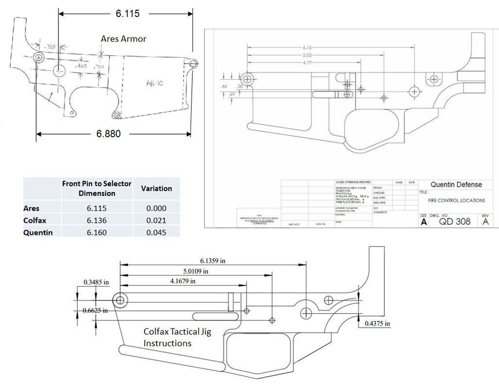
|
|
|
|
USA
|
[#23]
thanks for sharing! i'm using the exact same tool path. the Ray-Vin site is great and so is CNCGuns! it goes from a 0% to finish but I referenced the exact same drawing you did for a 7/16th's bit.
for my trigger and hammer pins, i think i'm going to go undersized and ream or go straight for a .154" bit instead of a 5/32" bit. what i will say is, i've looked at a lot of lowers that are being produced now and the drawing below has the 7/16" bit move +.032 and -.032 on the Y axis for the rear take down pin, and it stops at 5.916 on the X axis for an RDIAS (if you have one) or some other odd reason. that's not being done by a lot of manufacturers now. they're only setting up for 2 widths, the width for the hammer and trigger pin area, and the rear take down/auto sear pin area. i've looked at my BCM, Daniel Defense, Lancer, and Spike's lowers and they all have the same milling/pockets. i don't think that extra material is necessary. |
|
|
|
[Last Edit: AFCarbon15]
[#24]
Originally Posted By kaotic504:
thanks for sharing! i'm using the exact same tool path. the Ray-Vin site is great and so is CNCGuns! it goes from a 0% to finish but I referenced the exact same drawing you did for a 7/16th's bit. for my trigger and hammer pins, i think i'm going to go undersized and ream or go straight for a .154" bit instead of a 5/32" bit. what i will say is, i've looked at a lot of lowers that are being produced now and the drawing below has the 7/16" bit move +.032 and -.032 on the Y axis for the rear take down pin, and it stops at 5.916 on the X axis for an RDIAS (if you have one) or some other odd reason. that's not being done by a lot of manufacturers now. they're only setting up for 2 widths, the width for the hammer and trigger pin area, and the rear take down/auto sear pin area. i've looked at my BCM, Daniel Defense, Lancer, and Spike's lowers and they all have the same milling/pockets. i don't think that extra material is necessary. I use a 3/8 chucking reamer to square up the safety holes. I have one for the trigger/hammer holes, but since I started using USA made 5/32 carbide EM's, I don't use the reamer for those anymore. The holes are always "just right". Also, I negate the 5.916 altogether. Although for a RDIAS, I believe the shelf depth should be .675, I'll correct that later if I'm wrong as I'm going from memory here. I have seen where others only touch up the rear pocket and leave a "web" between the rear lug pocket and the FCG area. I don't think the extra material/strength is required, but I would be less work, certainly if using a jig and router. |
|
|
|
USA
|
[#25]
I see that the dimension for the Y axis of 0.031 from Ray-Vin's drawing has changed to 0.032. Does that 0.001 really make a difference? Also, if you pick up the butt face of the buffer tube with an edge finder, travel 1/2 the thickness of the edge finder, couldn't you just make this your zero. Of course you would have to subtract all the numbers given by 7.500". For example, the rear take down lug/pin area on the X axis is 6.558". If you take 7.500 ( the dimension from the buffer tube to the center of the front take down pin) and minus 6.558, you'll get 0.942. This way, you will only have to travel a max of 4.017 on the X axis instead of 6.558. Just asking here. I have never actually done an 80%, but I'm always looking for the least amount of work possible, I guess it's the laziness in me
|
|
|
|
[#26]
Originally Posted By AFCarbon15:. I have seen where others only touch up the rear pocket and leave a "web" between the rear lug pocket and the FCG area. I don't think the extra material/strength is required, but I would be less work, certainly if using a jig and router. Not needed on aluminum lowers, particularly for devotees of Nolo, but might add just a titch of extra strength for those milling out plastic or wooden lowers. |
|
|
|
|
[Last Edit: AFCarbon15]
[#27]
Originally Posted By olds442:
I see that the dimension for the Y axis of 0.031 from Ray-Vin's drawing has changed to 0.032. Does that 0.001 really make a difference? Also, if you pick up the butt face of the buffer tube with an edge finder, travel 1/2 the thickness of the edge finder, couldn't you just make this your zero. Of course you would have to subtract all the numbers given by 7.500". For example, the rear take down lug/pin area on the X axis is 6.558". If you take 7.500 ( the dimension from the buffer tube to the center of the front take down pin) and minus 6.558, you'll get 0.942. This way, you will only have to travel a max of 4.017 on the X axis instead of 6.558. Just asking here. I have never actually done an 80%, but I'm always looking for the least amount of work possible, I guess it's the laziness in me Yes, that 0.001 makes a difference. I've had a few uppers that would not go in if milled at 0.031. After the first one that I had to put back into the mill, I started checking them with an upper before I pull them out of the mill. .031 + .031 + .4375 = .4995. My machine is not accurate enough to do .0005, repeatedly. I agree you could easily zero X on a number of closer points. The layout of the pocket has a LOT of room for error. Y is a little more important than X for sure. Since I started AR308's and zeroing X on the bolt catch slot, I have considered changing to the same for AR15's. I would have to reprint and laminate all of my documents. But this whole thing has grown organically. As for Pre-drilling, it depends on your methods. If all you want to do is limit the time on the mill, pre-drilling will take time, but save time on the mill. (like if you are using a buddy's mill, but your drill press) Using a full sized bridgeport, I doubt you would save much time, but maybe a little. As for my experience with a mini-mill, I have found traversing between pre-drilled holes causes a LOT of chatter. It's a little easier on the nerves to just mill the whole thing. Even with a tool change from a 3/8 roughing end mill to a 7/16 finish EM, it only takes me about 30-35 minutes to mill the complete pocket. ETA some numbers. |
|
|
|
USA
|
[#28]
Originally Posted By AFCarbon15:
Yes, that 0.001 makes a difference. I've had a few uppers that would not go in if milled at 0.031. After the first one that I had to put back into the mill, started checking them with an upper before I pull them out of the mill. I agree you could easily zero X on a number of closer points. The layout of the pocket has a LOT of room for error. Y is a little more important than X for sure. Since I started AR308's and zeroing X on the bolt catch slot, I have considered changing to the same for AR15's. I would have to reprint and laminate all of my documents. But this whole thing has grown organically. As for Pre-drilling, it depends on your methods. If all you want to do is limit the time on the mill, pre-drilling will take time, but save time on the mill. (like if you are using a buddy's mill, but your drill press) Using a full sized bridgeport, I doubt you would save much time, but maybe a little. As for my experience with a mini-mill, I have found traversing between pre-drilled holes causes a LOT of chatter. It's a little easier on the nerves to just mill the whole thing. Even with a tool change from a 3/8 roughing end mill to a 7/16 finish EM, it only takes me about 30-35 minutes to mill the complete pocket. Originally Posted By AFCarbon15:
Originally Posted By olds442:
I see that the dimension for the Y axis of 0.031 from Ray-Vin's drawing has changed to 0.032. Does that 0.001 really make a difference? Also, if you pick up the butt face of the buffer tube with an edge finder, travel 1/2 the thickness of the edge finder, couldn't you just make this your zero. Of course you would have to subtract all the numbers given by 7.500". For example, the rear take down lug/pin area on the X axis is 6.558". If you take 7.500 ( the dimension from the buffer tube to the center of the front take down pin) and minus 6.558, you'll get 0.942. This way, you will only have to travel a max of 4.017 on the X axis instead of 6.558. Just asking here. I have never actually done an 80%, but I'm always looking for the least amount of work possible, I guess it's the laziness in me Yes, that 0.001 makes a difference. I've had a few uppers that would not go in if milled at 0.031. After the first one that I had to put back into the mill, started checking them with an upper before I pull them out of the mill. I agree you could easily zero X on a number of closer points. The layout of the pocket has a LOT of room for error. Y is a little more important than X for sure. Since I started AR308's and zeroing X on the bolt catch slot, I have considered changing to the same for AR15's. I would have to reprint and laminate all of my documents. But this whole thing has grown organically. As for Pre-drilling, it depends on your methods. If all you want to do is limit the time on the mill, pre-drilling will take time, but save time on the mill. (like if you are using a buddy's mill, but your drill press) Using a full sized bridgeport, I doubt you would save much time, but maybe a little. As for my experience with a mini-mill, I have found traversing between pre-drilled holes causes a LOT of chatter. It's a little easier on the nerves to just mill the whole thing. Even with a tool change from a 3/8 roughing end mill to a 7/16 finish EM, it only takes me about 30-35 minutes to mill the complete pocket. I agree, the best way is to check the work with an upper before you remove it from the mill. You make a valid point about the extra 0.001, which actually 0.002 in total. the rear dimension goes from .4995 to .5015. I just measured an upper's back lug and got exactly .4995. I too would go with 0.032. Nice write up. |
|
|
TX, USA
|
[#29]
By the way I have a 80% lower I messed up because I drilled the hole wrong. I bored it out and then epoxied an aluminum rod into it but that part won't hold (it comes off). I'm going to use something like alumi-weld (welding rod for aluminum that works with a propane torch), would that work?
|
|
|
|
[#30]
Originally Posted By taiwanluthiers: By the way I have a 80% lower I messed up because I drilled the hole wrong. I bored it out and then epoxied an aluminum rod into it but that part won't hold (it comes off). I'm going to use something like alumi-weld (welding rod for aluminum that works with a propane torch), would that work? If your lower is 7075, welding is generally not advised. Where is the hole? |
|
|
|
NC, USA
|
[Last Edit: deezbill]
[#31]
This is a good thread to start, OP. I like one of the reasons for it - to build confidence.
My pics here should help to give people confidence in that it was my first 80% lower completed, and it was done WITHOUT a jig. Forgive the dirty oil lines inside the pocket...I didn't clean it up before I took the pics. All I used was a small, 30 year old mini drill press, digital calipers, and a combination of blueprints (mainly Colt's originals and these that you posted on your first post). Only thing I had to do differently was that everywhere there was use of a 7/16" bit, I used a 3/8" bit because I didn't have a 7/16" bit at the time for some reason. I'm about 95% happy with what I did. All good info posted here, especially for fixes to mistakes. Again, I hope my pictures will inspire some to take on the challenge...especially, if they have the correct tools (unlike me!). In other words, if I can do it without a jig and no better tools, anyone can do it with the proper tools. 


|
|
|
NC, USA
|
[#32]
Originally Posted By olds442:
I see that the dimension for the Y axis of 0.031 from Ray-Vin's drawing has changed to 0.032. Does that 0.001 really make a difference? Also, if you pick up the butt face of the buffer tube with an edge finder, travel 1/2 the thickness of the edge finder, couldn't you just make this your zero. Of course you would have to subtract all the numbers given by 7.500". For example, the rear take down lug/pin area on the X axis is 6.558". If you take 7.500 ( the dimension from the buffer tube to the center of the front take down pin) and minus 6.558, you'll get 0.942. This way, you will only have to travel a max of 4.017 on the X axis instead of 6.558. Just asking here. I have never actually done an 80%, but I'm always looking for the least amount of work possible, I guess it's the laziness in me Your are suggesting changing your datum reference. Not advisable. There are tolerances in machining, nothing is always exactly where it is on the drawing, except the data references, as those are where everything is measured from. For the AR lower most locations are referenced off the front pivot hole. The point you reference (the back of the extension horn) is 7.500 -.006" from the reference point of the front pivot pin. If you start measuring everything from the back, as you suggest, your new locations could be .006" off. Also, it should be noted that the trigger pin is located relative to hammer pin hole to 0.0015 (one -and-a-half thousandths), and the X distance to the safety hole also has a .0015" tolerance. |
|
|
TX, USA
|
[#33]
Originally the hammer, trigger, and selector hole is about .2 inch too far forward. I'm getting another 80% lower to start over from with a jig.
Like I said originally I was working on a 308 lower and the blueprint is wrong... I just didn't have anything to reference from and no manufacturers will release any measurements. I bought some of that aluminum brazing rod because I hope I can at least salvage this one... I know 7075 shouldn't be welded but technically it's not welding, also the holes in the lower is not a structural component. |
|
|
|
[#34]
Added some more info and a crappy video. I'll probably redo the whole video, but you get the idea.
|
|
|
|
|
[#35]
Originally Posted By deezbill:
This is a good thread to start, OP. I like one of the reasons for it - to build confidence. My pics here should help to give people confidence in that it was my first 80% lower completed, and it was done WITHOUT a jig. Forgive the dirty oil lines inside the pocket...I didn't clean it up before I took the pics. All I used was a small, 30 year old mini drill press, digital calipers, and a combination of blueprints (mainly Colt's originals and these that you posted on your first post). Only thing I had to do differently was that everywhere there was use of a 7/16" bit, I used a 3/8" bit because I didn't have a 7/16" bit at the time for some reason. I'm about 95% happy with what I did. All good info posted here, especially for fixes to mistakes. Again, I hope my pictures will inspire some to take on the challenge...especially, if they have the correct tools (unlike me!). In other words, if I can do it without a jig and no better tools, anyone can do it with the proper tools. http://i1174.photobucket.com/albums/r613/deezbill/AR%20Lower/80%20Lower%201.jpg http://i1174.photobucket.com/albums/r613/deezbill/AR%20Lower/80%20Lower%203.jpg http://i1174.photobucket.com/albums/r613/deezbill/AR%20Lower/80%20Lower%202.jpg Very solid job. My first couple of lowers didn't turn out that nice and I did use a jig. I can now crank out a lower with a jig in about an hour and the look okay but all of them work 100%. |
|
|
|
|
[#36]
Sorry for the crappy video, but it's still cool to me.
|
|
|
|
|
[Last Edit: AFCarbon15]
[#37]
Pilfered this one from sixtysixdeuce. Hope you don't mind, just trying to help others

|
|
|
|
|
[#38]
what speeds are you guys running the end mills? i find i get alot of chatter especially on the deeper pocket. also is no one using coolant? i was using wd40 and it seemed to help a little although it made a big mess.
|
|
|
|
USA
|
[#39]
what speeds are you guys running the end mills? i find i get alot of chatter especially on the deeper pocket The speeds, feeds and depth of cut you can get away with are gonna depend on your machine, vise and cutter. I run a 7/16" 4 flute HSS at 1,500 for roughing and 2,500 for finish passes, I cut 0.625" deep, and move pretty quickly (about 6 IPM). But I'm running a 3,600 lb, 3 HP Lagun mill, and holding the lower in a large Palmgren vise. You won't be able to be so aggressive with a mini mill. Nowhere near. |
|
|
TX, USA
|
[#40]
I find that cutter and workpiece flex matters a lot more than machine rigidity.
What I mean is, when cutting deep pockets retract the end mill as far into the collet as you can, and use the shortest LOC end mill that you can to get the job done. Also make sure the clamping setup is rigid. A G0704 should be able to comfortably cut .200 deep in aluminum assuming you're using end mills that doesn't flex. I actually tested this by taking one of those 4" long 3/8" end mills and pushed the end mill into the collet, past the flute so only the required depth to mill the pocket stuck out (about 1.2"). This reduced chatter quite a bit, so much so I can actually shave materials off full depth fairly comfortably. Before it would chatter so much. A dull HSS end mill will not cut anywhere near as well as a good sharp carbide. |
|
|
USA
|
[#41]
Originally Posted By olds442:
I see that the dimension for the Y axis of 0.031 from Ray-Vin's drawing has changed to 0.032. Does that 0.001 really make a difference?... I personally hate sloppy upper/lower fit, so I go 0.030" and then start checking fit. When it "almost" goes I use hi-spot dye and sandpaper on a stick to get the last bit and a perfect fit. The result is a perfectly paired upper and lower. I'd advise everyone not to think of your 80% project as a shade-tree chance to cut corners. Think of it as an opportunity to build a better-than-factory weapon. It doesn't cost any extra money, just a little extra time. |
|
|
|
[#42]
Tag for later, I can get nail down the specs and kick out some better drawings.
|
|
|
|
NC, USA
|
[#43]
Originally Posted By Sixtysixdeuce:
The speeds, feeds and depth of cut you can get away with are gonna depend on your machine, vise and cutter. I run a 7/16" 4 flute HSS at 1,500 for roughing and 2,500 for finish passes, I cut 0.625" deep, and move pretty quickly (about 6 IPM). But I'm running a 3,600 lb, 3 HP Lagun mill, and holding the lower in a large Palmgren vise. You won't be able to be so aggressive with a mini mill. Nowhere near. Originally Posted By Sixtysixdeuce:
what speeds are you guys running the end mills? i find i get alot of chatter especially on the deeper pocket The speeds, feeds and depth of cut you can get away with are gonna depend on your machine, vise and cutter. I run a 7/16" 4 flute HSS at 1,500 for roughing and 2,500 for finish passes, I cut 0.625" deep, and move pretty quickly (about 6 IPM). But I'm running a 3,600 lb, 3 HP Lagun mill, and holding the lower in a large Palmgren vise. You won't be able to be so aggressive with a mini mill. Nowhere near. I used regular bits for drilling and 4 flute carbide endmills a friend gave me since he had a lot of bits where he works. I used a mini-press. I can't remember my speeds exactly, but I do remember drilling with speeds around 600-800rpm for the majority of the work. I never changed my speed until the very end using around 1100-1300rpm. The higher speed helped. I tried to keep my speeds around what some of the professional guys said from my research and on YouTube videos. However, of everything I read and watched, speeds were different. For the most part, people were generally in the ballpark regarding speeds. Just pay attention to the application of what you are drilling with consideration to what type and size bit you are using. Originally Posted By taiwanluthiers:
A dull HSS end mill will not cut anywhere near as well as a good sharp carbide. I found this out REAL quick on one of my drill bits. I was drilling out with a dull bit getting absolutely nowhere. I thought I wasn't using enough oil/lubricant, speed, etc. I tried a new bit I had laying around and it cut soooooo much better and cleaner with little chatter. So, make sure you have good bits. |
|
|
|
[Last Edit: AFCarbon15]
[#44]
Originally Posted By bluedxj:
what speeds are you guys running the end mills? i find i get alot of chatter especially on the deeper pocket. also is no one using coolant? i was using wd40 and it seemed to help a little although it made a big mess. For my 3/8 rougher, I run around 1800-1900rpm. My finish passes are with a long LOC 7/16 4-flute HSS I run full depth but only .005-.015 per pass. I run those a little faster, 2000-2100rpm. For the 3/8 rougher, I have a 3 flute and a 4 flute, I don't see much if any difference. Same with the 7/16 4 flute finishing EM, I have the same in HSS and in carbide, I really don't see any difference between the two. When taking heavier passes, the carbide flex is considerably less. But again, all of these are long LOC's 1-1/2" or more so I can get full depth clean up passes. From my experience anything faster may lead to galling. I do run 7075 dry. 6061 I have to run slower and with lubricants. Even with slower speeds and lube, 6061 likes to gall. Not knowing anything when I started, I have learned to drive based on feel and sound. A nice fluid hum or purr is better than a squeal or choppy growl. If you're getting chatter, squealing or shaking, you need to adjust. From my experiences on a mini-mill, faster rpm and slower feed rates are the easiest ways to reduce chatter. But if you're getting a high pitched squeal, you need to slow down increase your chip load, meaning you're not cutting enough material. I'm sure every machine is a little different. Any expert machinists, feel free to correct me if I'm technically wrong. These are just my own experiences. The guys that have made a living doing this work in production environments may have some easy standards that translate to our non-production quality machines. 
|
|
|
|
NC, USA
|
[#45]
Originally Posted By AFCarbon15:
For my 3/8 rougher, I run around 1800-1900rpm. My finish passes are with a long LOC 7/16 4-flute HSS I run full depth but only .005-.015 per pass. I run those a little faster, 2000-2100rpm. For the 3/8 rougher, I have a 3 flute and a 4 flute, I don't see much if any difference. Same with the 7/16 4 flute finishing EM, I have the same in HSS and in carbide, I really don't see any difference between the two. When taking heavier passes, the carbide flex is considerably less. But again, all of these are long LOC's 1-1/2" or more so I can get full depth clean up passes. From my experience anything faster may lead to galling. I do run 7075 dry. 6061 I have to run slower and with lubricants. Even with slower speeds and lube, 6061 likes to gall. Not knowing anything when I started, I have learned to drive based on feel and sound. A nice fluid hum or purr is better than a squeal or choppy growl. If you're getting chatter, squealing or shaking, you need to adjust. From my experiences on a mini-mill, faster rpm and slower feed rates are the easiest ways to reduce chatter. But if you're getting a high pitched squeal, you need to slow down increase your chip load, meaning you're not cutting enough material. I'm sure every machine is a little different. Any expert machinists, feel free to correct me if I'm technically wrong. These are just my own experiences. The guys that have made a living doing this work in production environments may have some easy standards that translate to our non-production quality machines.
Originally Posted By AFCarbon15:
Originally Posted By bluedxj:
what speeds are you guys running the end mills? i find i get alot of chatter especially on the deeper pocket. also is no one using coolant? i was using wd40 and it seemed to help a little although it made a big mess. For my 3/8 rougher, I run around 1800-1900rpm. My finish passes are with a long LOC 7/16 4-flute HSS I run full depth but only .005-.015 per pass. I run those a little faster, 2000-2100rpm. For the 3/8 rougher, I have a 3 flute and a 4 flute, I don't see much if any difference. Same with the 7/16 4 flute finishing EM, I have the same in HSS and in carbide, I really don't see any difference between the two. When taking heavier passes, the carbide flex is considerably less. But again, all of these are long LOC's 1-1/2" or more so I can get full depth clean up passes. From my experience anything faster may lead to galling. I do run 7075 dry. 6061 I have to run slower and with lubricants. Even with slower speeds and lube, 6061 likes to gall. Not knowing anything when I started, I have learned to drive based on feel and sound. A nice fluid hum or purr is better than a squeal or choppy growl. If you're getting chatter, squealing or shaking, you need to adjust. From my experiences on a mini-mill, faster rpm and slower feed rates are the easiest ways to reduce chatter. But if you're getting a high pitched squeal, you need to slow down increase your chip load, meaning you're not cutting enough material. I'm sure every machine is a little different. Any expert machinists, feel free to correct me if I'm technically wrong. These are just my own experiences. The guys that have made a living doing this work in production environments may have some easy standards that translate to our non-production quality machines.
Reading this post reminds me of a lot of things that the sounds told me. The high pitched squeal that I was getting was when I was using a dull bit which concurs with AFCarbon15's post. He did a good job of describing what you need to understand with certain sounds. |
|
|
|
[#46]
Bump to keep er outa the archives. Been a little more 80% talk as of late. Hopefully they come through with the new sub forum.
|
|
|
|
|
[Last Edit: PursuitSS]
[#47]
Originally Posted By AFCarbon15:
Bump to keep er outa the archives. Been a little more 80% talk as of late. Hopefully they come through with the new sub forum. I'm going to "bump" VA-gunnut in around a week or so and see if there has been any progress. |
|
|
|
|
[#48]
Originally Posted By AFCarbon15:
Bump to keep er outa the archives. Been a little more 80% talk as of late. Hopefully they come through with the new sub forum. And another. I do have some more milling pics and info, but I've been spending more time doing than documenting. |
|
|
|
|
[#49]
Originally Posted By AFCarbon15: And another. I do have some more milling pics and info, but I've been spending more time doing than documenting. Originally Posted By AFCarbon15: Originally Posted By AFCarbon15: Bump to keep er outa the archives. Been a little more 80% talk as of late. Hopefully they come through with the new sub forum. And another. I do have some more milling pics and info, but I've been spending more time doing than documenting.
|
|
|
|
TX, USA
|
[#50]
Why put that little offset notch above the selector switch? So many manufacturers are making that part strait these days that it doesn't really seem taboo anymore. I have mega lowers and they all are strait.
http://www.megaarms.com/ar-15/lower-receivers/forged-lower/ 
|
|
|
 Win a FREE Membership!
Sign up for the ARFCOM weekly newsletter and be entered to win a free ARFCOM membership. One new winner* is announced every week!
You will receive an email every Friday morning featuring the latest chatter from the hottest topics, breaking news surrounding legislation, as well as exclusive deals only available to ARFCOM email subscribers.

AR15.COM is the world's largest firearm community and is a gathering place for firearm enthusiasts of all types.
From hunters and military members, to competition shooters and general firearm enthusiasts, we welcome anyone who values and respects the way of the firearm.

Subscribe to our monthly Newsletter to receive firearm news, product discounts from your favorite Industry Partners, and more.
Copyright © 1996-2024 AR15.COM LLC. All Rights Reserved.
Any use of this content without express written consent is prohibited.
AR15.Com reserves the right to overwrite or replace any affiliate, commercial, or monetizable links, posted by users, with our own.


