Warning


Close

Confirm Action

Are you sure you wish to do this?

Confirm Cancel
BCM
User Panel

Site Notices
Posted: 11/20/2023 2:43:40 PM EDT
Howdy folks.  I originally posted this on a number of forums back in 2014 but I wasn't a member here at that time.  Today, I was looking around this site and discovered this sub-forum and I thought you folks might be interested in this.  So, now I'm re-posting it generally unedited here for your information/entertainment.  We begin now.


As usual with my "in detail" essays, this is going to take me several days and multiple posts to complete. I try to provide useful information on subjects that I have wanted information about for many years but could not find. My thinking is that, if I wanted such information, I'm sure that others must have as well and these posts seek to provide that service for people who are in the same boat I was in. Hopefully, I will succeed and not bore you folks to death in the process. As always, if I do not provide information which you seek, please do not hesitate to contact me and I will gladly help you if I can. As you look through this, you will notice that I have covered up the serial numbers. I hated to do this but I feel that the current political climate in this country necessitates such actions....it's very sad to feel this way. I'm starting this one with a little History because I needed to write something in an effort to keep my mind busy. If you don't care about the background or simply hate my writing/rambling thoughts, just skip to the pictures and have at it! Thank you for your time and good luck getting through this without falling asleep.


        When most people think of roller locked rifles, they think of the German arms manufacturer Heckler & Koch and their G3 rifle.  To a slightly lesser extent, Spain's Cetme comes to mind as well.  Both of these rifles are direct descendants, more final products really, of the prototype STG45 designed by Mauser Werke in the waning days of WWII.


         The STG45 was Mauser's answer to Germany's quest for the next generation of infantry rifle.  It was an amalgam of two classes of small arms, seeking an efficient balance between the ranged capability of the full sized rifle  and the close range volume of the submachine gun.  It was also designed to make extensive use of stamped parts in an effort to speed up the manufacturing process and conserve precious resources.  Additionally, it eliminated the need for a gas piston and associated parts, hereby simplifying the design and making it more reliable at the same time.


         To this end, it employed a delayed blowback system using a trunnion with recesses machined into it, a bolt head with moveable rollers that would lock into those recesses and a wedge shaped camming piece that controlled how long those rollers kept the bolt head locked into the trunnion.  These parts, working in unison against the rearward forces created by the detonation of the powder in the cartridge, kept the breech safely closed until the bullet had exited the barrel and pressures had dropped to acceptable levels.  Mauser called it a "half locked" design and, while locking rollers had been employed in previous firearms (most notably the German MG42), this novel setup was something never before seen.  Whereas the STG44 had revolutionized the concept of military rifles, the STG45 revolutionized the design of that concept.  It was set to be Germany's new "Storm Rifle" replacing the STG44 and entirely eliminating the need for both a standard long range rifle and a short range submachine gun.


         By the spring of 1945, multiple advanced prototypes had been assembled and mass production was on the horizon but the war ended before the project could be brought to fruition.  But, in a vein similar to many of Germany's technologically advanced projects, this was not the end of the STG45.  In the late summer of 1950, Mauser engineer Ludwig Vorgrimler moved to Spain, taking much of the firm's STG45 development data with him.  The result was the CETME rifle and, because of Belgium's refusal to allow a German firm to build the FN FAL under license, the HK G3.  The rest, as they say, is History.  But there is another History; one most people are unaware of involving the Swiss manufacturer Schweizerische Industrie Gesellschaft (SIG) and its own roller lock derivative of the STG45 known as the SIG 510.


         The Swiss have always been known for producing extremely high Quality firearms that employ advanced design characteristics as well.  Proof of this is readily seen in the well known K31 straight pull bolt action carbine which was accepted for service in 1931.  This carbine was built to the highest Quality standards of any rifle in the world at that time and common issue examples rivaled the best sniper rifles of other nations.  Dating back to the latter part of the 19th century, the straight pull bolt design was lightning fast to operate, smooth as glass and extremely durable.  It was also very expensive to produce.  That last part didn't bother the Swiss.  In fact, spending lavish amounts on the Quality of their equipment was standard fare.  What DID bother them however was their eventual realization of the fact that the self loading select fire rifle was the way of the future.  By the early 1940's, they were already at work on various designs, ranging from fairly typical gas piston systems to blow forward actions.  In the end though, all were found wanting for one reason or another.  But the emergence of Mauser's half lock design must have really impressed SIG engineers.  Exactly how or when they became aware of it, whether it was through the original STG45 project or through continuing development being carried out in France and Spain post war by ex-Mauser  engineers, I do not know.  What I do know is that, by the early 1950's, SIG was working on a roller lock design of their own.  The culmination of this effort was the SIG 510-1.


         Accepted by the government in 1957 (two years before Germany accepted the G3) as the Sturmgewehr 57, the 510 had the honor of being Switzerland's first standard issue select fire rifle.  In some ways, it was very similar to the STG45 and Cetme designs.  The basic operating principle was the same and the rifle made use of sheet metal stampings for the majority of both the receiver and trigger housing.  Beyond that, the Swiss had parted ways with the German and Spanish designs and had, as usual,  created a firearm that was characteristically "Swiss".  Whereas the Cetme was originally designed for an intermediate sized round and had been modified to accept a full sized cartridge, the 510 had been intended for use with the standard 7.5x55 cartridge from the outset.  Because of this, the various components of the 510 appear somewhat massive when compared to their German and Spanish counterparts.  This is especially apparent when comparing the bolt heads, rollers and locking wedges.  The trunnion is located outside as opposed to inside the receiver for this reason as well.  There are many other details about this rifle that bear mention and that is part of the reason for this work.  But the main reason is to provide careful and detailed first hand information about this interesting and, unfortunately, seldom encountered rifle in the hope that others will find it useful whether it be for research or just plain 'ol curiosity.


         The example that we will be studying is the "Americanized" version of the SIG 510-4.  Chambered in 7.62x51, it is called the 510-7 by SIG but is known here in the United States as the American Match Target or AMT and it is marked on the top of the trunnion as such.


     For scale and comparison purposes, many of the photographs will also include various parts of an HK91, itself the civilian version of Germany's G3 rifle.  One of the common misconceptions about the SIG is that it is a large and ungainly rifle.  Visually, that certainly appears so what with its look of cobbled together boxes and tubes.  In reality though, it is quite slender and actually about the same length as its German counterpart and significantly shorter than its Belgian/Austrian and American contemporaries as can be seen below:


     In fact, the first time I saw one in the flesh, I was immediately struck by how small it appeared for a .308 battle rifle.  It almost looked as if it was a miniature of the many 510s I had previously seen only in pictures.  It is heavy though.  It would be prohibitively heavy were it not for the fact that SIG used aluminum for some of the less critical parts such as the barrel jacket, bipod legs and butt plate.   This is not to say that the 510 is in any way cheaply made of fragile.  On the contrary, it was built to the highest standards, using heavy gauge steel that is both spot welded AND brazed for maximum durability.  Upon even the most casual inspection, it is immediately obvious that both cost and ease of manufacture were not a serious consideration.  Rather, reliability, durability and longevity were the driving factors behind the design.  As you would expect of a Swiss made product, fit and finish approaches the realm of art.  Machining marks are almost nonexistent, bluing and phosphate are near flawless and inspection stamps are usually as clear as if they were engraved (the serial numbers are in fact engraved).  The walnut stock and forearm are impeccably finished as well.  Simply put, the SIG is the highest Quality military firearm I have ever encountered.


    But I have droned on long enough.  In my next post, we'll begin to get to the good stuff...pictures!  Later, we'll start ripping stuff apart and look at the guts and other assorted goodies.  We might even have a sword fight using the AMT and HK91 as our swords!!  Well, maybe not that last part but we will have fun looking at all the cool metal bits and rolling thingies!  Believe it or not, this post took me a looong time to type because I'm a slow hunt and peck type of guy so I'm done for the night.  I think slowly too.  I'll be back at it soon though.  Thanks for your time and Gute Nacht!

Link Posted: 11/20/2023 2:51:30 PM EDT
[#1]
Next we will look at the outside of the rifle.  We'll start at the muzzle, work our way down one side and then up the other, just like cleaning a motorcycle!  Alrighty then, here's the muzzle:


This picture gives a good clue about what to look for when determining whether or not you are looking at the ACTUAL muzzle.  What???  That previous statement will become clear in a moment.  A 510 barrel has no muzzle attachment screwed onto it.  Instead, the barrel is turned down and the muzzle brake or flash hider (there is some argument about which it actually is) is formed as the barrel blank is turned on the lathe.  The nodes that form the grenade launching rings are cut at the same time.  On a military issue 510, the end of the muzzle is counter bored in a conical fashion instead of being flat on the front as you see above.  On all but the earliest AMT's imported into the US, the muzzle brake and grenade launching rings were omitted in order to make the rifle more "sporting".  There is argument about whether military barrels were turned down for this or were made from scratch without these features.


Here is the real muzzle:


The rifles seem to have been imported with the simple threaded muzzle seen above and importers then attached whatever muzzle device they saw fit.  For this reacon, AMT's show up with various different bits on them.  The one shown here was made by a man named Estes Adams.  He reproduces various hard to find items for various rifles.  One of his products is a steel screw on attachment designed to give the AMT a more original 510-4 appearance.  When it is attached, you cannot tell that you are not looking at the original barrel unless you know exactly what to look for.  The giveaways are the flat muzzle and the fact that the grenade launching nodes are not as prominent because the barrel now has a larger diameter.  His products are absolute top notch Quality.


Here's where Mr. Adams faux barrel attachment meets the front sight base.  It blends seamlessly:


The line seen just in front of the node is not the end of the attachment but simply a mark left by the lathe.


Here's the attachment removed from the barrel:


A side profile on the rifle:


And the barrel as it was originally imported:


Next up is the front sight and sight base.  The base is made of aluminum and is pinned to the barrel jacket.  It is not meant to be removed from the jacket.  The front sight ears and post are made of steel.  Here's the front of the assembly:


To adjust windage, the allen head bolt is loosened and you simply push the sight left or right.  The hole below the allen bolt has a plunger in it on the military models used for the attachment of a luminous attachment for using the sights in low light conditions.  Elevation is adjusted by slipping a special wrench over the sight post and screwing it up and down.  Also seen is the punch mark applied at the factory when the rifle was sighted in and, to the right of the picture behind the sight base, is the front sling attachment point (also made out of aluminum).


Here's the front sight seen from the side:


You can see the slot cut so that the base pinches the sight when the allen bolt is tightened, thus holding it tightly.  Also seen is one of the pins that holds the sight to the barrel jacket.  To the left of the picture is the top of the bipod.  The bipod will swing 360 degrees and is stowed on top of the barrel jacket.  Unlike the HK bipod and like the FAL one, it has no locking mechanism.  It just uses springs and detents to hold it open or closed.  On the military version, it can be disassembled and refitted onto a slot machined out in the rear section of the barrel jacket if desired.  The AMT jacket has that slot but the bracket used for attaching it to the trunnion precludes the bipod from being moved.


The bottom of the sight base showing a flat spot where the bayonet lug was removed.  All aluminum parts on the rifle appear to be black anodized NOT painted:


Link Posted: 11/20/2023 2:53:17 PM EDT
[#2]
I've shot a friend's AMT.  Terrific rifles.
Link Posted: 11/20/2023 2:56:14 PM EDT
[#3]
Next up is a picture showing how the bipod is put together:

I'd like to take it apart and show each piece individually but I hesitate to do so because of past experiences with nyloc nuts loosening after being removed.  These are old and I'm just going to leave them as they are.  The bipod legs are aluminum but everything else is steel such as the top and bottom parts of the attachment yoke, detent plates (they are separate parts and not part of the bottom yoke), bolts and nuts.  I think (but I'm not sure) that there is a steel bearing inside there too so that the bipod rotates on steel instead of the aluminum jacket.


Check out this detail shot of the inspection mark on one of the bolts.  The Swiss are a little obsessive about nice clean stamps.  The only place I could find partial stamps is one place on the trunnion which we'll see later.  This shot also shows just how tightly everything fits together with minimal gaps and movement and it gives you a good idea about how thick the barrel jacket is by looking at the edges of the cooling slots.


Moving on to the hand guard, we see that it is held  in place by one screw and toothed lock washer.  First we'll look at it removed so that you can see the inside of it:

 The extra shiny look comes the Automatenfett that has not yet been wiped off.  That's the grease that the Swiss use for cleaning, lubricating and storing their firearms.  The older stuff for the bolt action rifles was a yellowish color and was called Waffenfett.  The Automatenfett is a dark slate gray stuff that is slightly thinner for use in automatic rifles.  The entire insides of this rifle were coated in the stuff and I could find no trace of carbon so I don't think the poor thing's ever gotten range time once imported.  That will change soon enough.


Here's the hand guard installed:


With the hand guard removed you see this:

We're looking at the bottom of the barrel jacket and the aluminum bracket used to attach it to the trunnion.  To the left we can see the front of the magazine well.  The bracket is held to the jacket using four rivets.  The hole in the center of the picture is where the hand guard screw goes.  To the left of the screw hole we see a reinforcement rib and to the left of that we see the single bolt and nyloc nut that attaches everything to the trunnion.  If you remove this nut and bolt, the entire jacket, front sight, bipod...everything slides off the front of the rifle leaving you with just a barrel sticking out the front of the receiver.  There is absolutely zero movement between the barrel and jacket when this bolt is attached.  You would think that it's all one piece.   Now THAT'S Swiss precision!


Here's the left side of the bracket:

Several other things are of interest.  To the right of the picture is the trunnion with the carrying handle coming out the front top. The trunnion is cast as is evident by the rough stippled surface of it. Just below the handle is a thin groove.  That groove and the tube to the left of it are part of the trunnion but they have been machined smooth.  Moving left, we see the barrel with a flat spot on it for a wrench so that it can be torqued into the trunnion and then we get to the jacket.   On the jacket between the rivets we can see another groove this is the rear attachment point for the bipod on the 510-1.  As stated earlier, the bipod will not mount here on the 510-4 or the 510-7 (AMT).


Right side of the bracket:

The round thing on the trunnion with a circlip around it is one of the locking recesses for the rollers.  Over time, these recesses wear.  When they wear enough, the rifle is no longer safe to fire because it will not properly lock.  On the G3 and CETME, that's the end of the rifle.  On the SIG, you just remove the circlip, pop out the worn locking recess.  Then you replace it with a new one and a new circlip, check your bolt gap and adjust if necessary with different diameter rollers.  You're back in business!  Below the locking recess is a symbol of some sort molded into the trunnion.  I have no idea what that signifies but I would like to.


Here's one last shot of this area taken to show the hole machined out of the trunnion for the front magazine locking lug.  This is hidden when the hand guard is in place.  of course you can still see it when looking up into the magazine well.  out of fpcus in the background, we can see the neato aluminum cocking handle carried over from the K31.  I like to believe that this was done out of a sense of tradition but I have no proof of that.


Link Posted: 11/20/2023 3:06:24 PM EDT
[#4]
Next up is the center section of the rifle.  It's made out of a combination of stamped as well as machined steel and built with typical Swiss quality.  Unlike most manufactures who simply spot weld the machined bits to the stamped bits, SIG goes a step further and also brazes everything together.  I'm neither an engineer nor a metallurgist so I don't know the exact method for getting all that stuff done but I do know this much.  The spot welds were used to hold the parts in place before everything was heated up crazy hot (how's that impressive technical jargon for ya?)  and the brazing was done.  The purpose of this is to hold all mating surfaces together across their entire surface not just at the spot welds.  They wanted to make sure that thing would last until the invading alien hordes came from space in the 24th century I guess.  Because of the brazing, there are no gaps anywhere where two surfaces meet.  The joints also have a slight copperish golden hue that can easily be seen in the right lighting conditions.  I'm assuming those high temperatures are part of the reason some of the bluing is a nice plum color as well.


Let's start with the top of the trunnion:

The top of the trunnion has been machined smooth.  To the extreme right of the photo we can see a number on the barrel.  This number is not connected to the rifle serial number on any example known.  It has something to do with barrel production stuff at the factory so don't wig out about the barrel number not matching when looking at buying one of these rifles. Some barrels seem to be not marked at all.....I don't know.  The roll pin near the front of the trunnion holds the carry handle in place.  Incidentally, the plastic carry handle is molded to the metal handle rod and is not removable.  Behind this pin is a little circle.  This is the loaded chamber indicator and it sticks up when the rifle is loaded.  Then we have the model designation engraved (not stamped) "SIG - AMT".  The white paper and tape is covering the engraved serial number.  The serial numbered parts on these rifles are as follows:  Barrel jacket, Receiver, Trigger Group, Stock (steel part, not the wood), Bolt Head and Bolt Carrier.  The slotted screw holds the spring inside the receiver for the loaded indicator.  The little plum colored bit behind the screw is where the front of the scope mount fits.  The rear of the scope mount locks into the front of the rear sight.  I don't have one of those yet but I will post it when I do.  Clearly seen where the mounting point meets the trunnion is the copper hue I spoke of earlier where parts are brazed together.


When cleaning the bore, the chamber indicator must be lifted out of the way or it will interfere with the cleaning rod.  This is done by using a little two purpose tool included in the handy dandy cleaning kit issued with every rifle.  The primary function of this tool is as an inspection mirror used to shine light up the bore but the handle of this mirror doubles as the tool for holding the indicator up out of the way for cleaning:


A view up into the magazine well.  Bolt carrier is on the left and bolt head is on the right:

Here we see the first obvious indication that this is a roller locked rifle and HK guys will immediately recognize this view.  Acceptable bolt gap is between .5 - 1.1 MM, much larger than HK's .25 - .5 MM.  The spring looking thingee on the bottom of the bolt head is indeed a spring.  We'll talk about that later.  Notice that the magazine well is part stamped receiver, part cast trunnion and part stamped/milled trigger box.


Just a few more pictures showing this area.  Things to take notice of are how well seams meet up, the nice purple hue to the bluing and how subtle the spot welds are.  It is beautiful but, when looked at objectively, it is overkill:


That last picture shows two partial stamps on the flat part of the trunnion in front of the locking recess.  They are they only partial stamps I could find on the entire rifle.


Right side of the trigger housing and receiver:

Starting from the top, we have the rear sight looking decidedly like the one used on the FAL.  We'll take a closer look at it later but notice that there is a roll pin at the front of the base to keep the slider from coming off the front.  You can just barely make out another roll pin at the rear of the base.  Also, at the front of the sight base is a conical hole.  This is the rear attachment point for the scope mount.  To the right of the picture, we have the non reciprocating charging handle and behind it can be seen the slot that it runs in.  There is a metal plate attached to the top of the receiver that bends down to stabilize the charging handle so that it does not wobble in the slot.  The rear of the slot widens and there are cutouts in the top plate so that the charging handle can be removed for cleaning or replacement.  The thingee at the rear of the receiver that looks like a "T" laying on its side is the milled rear trunnion.  It gives the back of the receiver strength and acts as the mounting point for the stock.  In the ejection port is the bolt carrier.  The slot cut into the carrier has a small rectangle in it.  This is the pivoting side of a bar that transfers the hammer strike to the firing pin.  It sounds complicated but it's actually very simple and will be covered in detail later.  The bar below the ejection port that the trigger box fits up against is a milled receiver reinforcement plate that is brazed and welded to the receiver box across its entire width.

Notice that the trigger group assembly does NOT attach at the front using a pin like a military issue G3 or a shelf like a civilian HK91.  Instead, it has a finger on each side that engages with tabs stamped and bent out of the magazine well area of the receiver shell.  At the rear, it is held in place by a pushpin. We'll take a closer look at this pin compared to an HK one later.  The pistol grip is attached to a stamped tab sticking out the bottom of the trigger group using two screws and nyloc nuts.  The white painted rectangle is a machined part that fits into a notch cut into the trigger housing and denotes that this rifle is modified for semi automatic fire only.  If it were select fire, this part would be turned around and the painted side hidden.  The circle below the white rectangle is the end of the safety axle.  Forward of that is the trigger pin.  The largest pin is the hammer pin and then we have the axle pin for the magazine release spring.  At the front of the trigger guard, you can see the magazine release lever hanging down.  Push forward on this and rock the magazine down and forward just like an AK.  The bent finger looking contraption that extends forward from the trigger guard is the winter trigger. This folds down for use with heavy gloves.  It pushes on the silver pin seen on the trigger and has the added (and probably unintended) advantage of giving you extra leverage when pulling the trigger, greatly reducing the pull required.  Here it is engaged and ready for use:


Close-up of the trigger guard showing the double roll pin used as the axle for the magazine release lever:


Grip serrations on the magazine release:


There is an adjustment nut on the bottom of the trigger box shown here:

This is NOT for adjusting trigger pull but rather for adjusting let off.  It controls how much of the sear surface contacts the notch in the hammer and it is preset at the factory.  DO NOT meddle with it unless you know exactly what you are doing or you may make the rifle unsafe when cocked.  Notice all the funky grease all over the place!


Rear sight from the side and the rear of the cocking slot.  Clearly seen are the front and rear roll pins keeping the slider from sliding off:


The rear sight is graduated from 100-600 meters:


Pretty push button for rear sight adjustment:


Here is the bottom of the pistol grip:


It is hollow for storage of the whatever you want to stick in there.  Just stick something into the hole to disengage the latch and slide the bottom cover to the rear:


The bottom cover after removal:


 When we start taking things apart, we'll break out the HK91 and look at some interesting comparison shots between the two.  As always, thanks for your time.
Link Posted: 11/20/2023 3:13:16 PM EDT
[#5]
In today's post, we finish up the outside of the rifle.  Picking up where we left off puts us at the stock.  On the bottom is this little button:

Similar to the MG42 machine gun, you simply press this button and rotate the stock 45 degrees counter-clockwise.  Then it will just pop off the rear of the receiver.


On the top we have index marks:

There are three of them.  One is mark is on the rear receiver trunnion and two are on the milled stock trunnion.  These marks are not really necessary for disassembly because the stock will only rotate one way so you can't screw it up.  The index marks come in handy for reassembly though.  Notice that there is an index line on the right corner of the stock trunnion.  Upon reassembly, you line this mark up with the one on the receiver trunnion, push (because the recoil spring inside is pushing back), and rotate the stock 45 degrees clockwise.  You will hear a "click" as the push button on the bottom snaps into place.  Done.  The third line is on the top of the stock trunnion and lines up with the index mark on the receiver trunnion when everything is in place.  In my opinion, it is pointless because it has no use.  The pushbutton give an audible click and the stock is locked.  You don't need to look at a mark to know what's going on.  But then this IS over engineered Swiss equipment.   Also seen in the above photograph is SIG's manufactured stamp and a piece of paper covering up the serial number.


Here is the butt plate:


Nothing much to say here.  It's made of heavy gauge aluminum.  The remove the wood part of the stock from the stock frame, just remove the screw and it's toothed lock washer.  Then the wood and aluminum sling attachment just comes off the back and you end up with this:


Inside the tube is the semi-captive recoil spring.  I say semi because, after you remove the stock, the spring won't fall out.  It's just held in by friction though and will easily pull out but we'll take a look at that later once we get to the guts.  The sling mount just inserts into a slot in the wood and the small hole ends up going over the little round nub welded in place sticking out the end of the tube.  That nub also has a threaded hole for the stock screw.


Here's a picture of the slot cut into the wood:


The rear end of the stock:


And the front end showing a little Pac-Man stamp:


Moving to the left side of the receiver now:

Dig that safety switch!  It's huge and not very ergonomical....no simple flip of the thumb with that one!  The tape is again covering the serial number.  Notice how the nyloc nuts are splined and the pistol grip has corresponding cutouts for those splines.  The importers mark is engraved similar to the serial numbers.  While the work is not as fine as SIG's, it still very well done and is much better looking than a stamp.  It's a nice touch.  The "1" and "S" markings are painted and are finely done although this picture makes them look terrible.  Whether the marks were engraved or stamped, I do not know but I would lean towards the latter because I'm almost positive that they are done at some point when the receiver is still essentially flat stock.  The only other important thing to notice in this shot is the area to the right (or rear, depending on your perspective) of the importer mark where the top of the receiver steps in.  This feature has to do with ejection and we will be referring back to it later.


That's it for the moment.  In the next post, we start looking at the insides and comparing individual parts and components to an HK91.  We'll start the comparison with both rifles field stripped.  Here's a preview of the first shot used in that post:


Link Posted: 11/20/2023 3:32:25 PM EDT
[#6]
In this post, we will begin looking at the internals of the 510 and compare some of the various bits to an HK91.   Let's start with a picture of both rifles field stripped:


Getting to this point is very simple and straight forward for both rifles.

HK91:

1.  Remove the magazine.

2.  Charge the rifle and assure that it is not loaded.  Leave it cocked.

3.  Remove both takedown pins and place them in the storage holes located near the rear of the stock.

4.  Remove stock.

5.  Remove trigger group.

6.  Charge rifle again and slide bolt group out the rear of the receiver.

7.  Rotate bolt head slightly less than 180 degrees (alignment lug will appear in window on bottom of bolt carrier) counter-clockwise when viewed from front and remove bolt head.

8.  Continue to turn locking wedge counter-clockwise until it pops out of carrier.

9.  Remove firing pin and spring.

For the SIG:

1.  Remove the magazine.

2.  Charge the rifle and assure that it is not loaded.  Leave it cocked.

3.  Press takedown latch on bottom of stock and rotate stock 45 degrees counter-clockwise until indexing marks align.  Remove stock.

4.  Press takedown pin button on right side of trigger group and slide pin to the right.  It may be left captive in trigger group or removed.

5.  Remove trigger group.

6.  Tilt muzzle up sharply and catch bolt group as it falls out the rear of the receiver.

7.  Slide charging handle to rear remove.

8.  Remove transverse pin from bolt head by pushing it from right to left.

9   Separate bolt head from carrier.


The HK uses two pins.  This is necessary because of the force imparted on the stock assembly by the recoil of the bolt group.  If only one pin was used, the receiver would be damaged over time.  The SIG only uses one pin because it just holds the rear of the trigger group in place and does not encounter any recoil forces.  To deal with recoil, the SIG's stock uses four machined "claws" (for lack of a better word) which grab the lugs that are machined into the trunnion on the rear of the receiver.

It would seem that the HK has the advantage here because the firing pin is removed during a normal field strip but this is slightly deceiving.  While the SIG's is not removed during a basic field strip, it is easily removed without any tools.  For reassembly, all that is needed is your issued Swiss Army Knife or part of your issued cleaning kit rod.  Actually, the SIG has the advantage because its bolt group can be completely stripped without tools at all whereas the HK requires a hammer and a punch.  And good luck reassembling the bolt head locking lever to the carrier in the field without massive frustration and/or failure!  To be fair though, how often do you REALLY need to remove either the locking lever or the rollers?  Pretty much never.

Notice how HUGE the SIG's bolt parts are compared to the HK.  Lets take a closer look at those bits.

First, the bolt groups assembled.

Left side:


The HK carrier has a bolt head locking lever that can be seen in this shot.  This is one of the elements (along with mass, locking wedge/trunnion/roller geometry and recoil spring K factor) that keeps the action locked until the bullet is safely out of the barrel.  The tension spring for this lever is crazy strong and it is THE reason that the bolt group requires some manhandling when taking it apart and putting it back together.  The SIG has no such part so the bolt head will flop around back and forth on the carrier, being held on only by the transverse pin (seen to the top rear of the roller).  Towards the rear of the carrier, you can see moving side of what SIG calls the "impact lever".  This is the bar that the hammer hits in order to fire the firing pin.  You see, in order to keep the receiver box height to a minimum, the recoil spring presses against the rear of the carrier level with the plane of the firing pin.   This means that the hammer cannot hit the firing pin directly because the recoil spring would be in the way.  In order to get around this problem, the designers used this impact lever which allowed them to locate the hammer to the left of the rifle's center line.  It was a simple and elegant solution that also acts as the firing pin retainer.

Right side:


The blue rectangles are bits of post-it-notes covering the engraved serial numbers.  In the middle of the carrier is the pivot side of the impact lever and above the blue rectangle on the bolt head is the end of the transverse pin.  At the front of the HK bolt head is seen the extractor.  WE didn't see one on the left side of the SIG unit and now there is none on the right side. Where in the heck is it on the SIG?

It's here....in the center on the bottom:


The extractor is a piece of spring steel that is held at its rear by a "T" slot machined into the bolt head.  While removable, it is NOT recommended to do so.  The ejector also helps in extraction and we'll se a shot of that in a bit.

Rear of bolt groups:


On the right is the HK carrier with its firing pin sticking out the back.  On the left is the SIG and you can't see the firing pin.  What you do see in the center of the carrier is the machined area where the front of the recoil spring engages.  To the left is seen the impact lever.  The thing sticking up at the front is a thick tab that is brazed into a slot cut into the carrier.  This tab serves two purposes.  First, it is what the non reciprocating charging handle presses against to pull the bolt group to the rear.  Second, it is the surface that hits the rubber buffer located in the stock.  We'll look at the buffer later.
Link Posted: 11/20/2023 3:45:19 PM EDT
[#7]
Here are a couple shots with the bolt head removed from both carriers.  Not much to say here other than look at that pile of parts in the background.  Also, I used black electrical tape to cover the serial number instead of post-it-note because this was a different day of taking pictures:


Let's take a closer look at the locking wedges:

The HK wedge is resting on the takedown pins so that it is on the same level for comparison purposes.  That will be obvious to an HK/Cetme owner but not everyone owns a roller lock so I should clarify.  The wedge on the SIG is part of the carrier and was machined out of the same block of steel as the carrier.  Notice how much bigger an beefier it is.  As stated earlier, the reason for this is the fact that the SIG was designed from the beginning for the full sized 7.5x55 cartridge  which is on par with a 30.06.  That makes it actually overbuilt for the 7.62x51 cartridge.  The HK and the FAL were both originally designed for the 7.92x33 cartridge which was an intermediate sized round.  Those designs were then stretched almost to their limits to accommodate the 7.62x51.  To many (myself included), this created aesthetically pleasing rifles....some would even call them beautiful.  Compared to them the SIG is ugly but, like a chubby girl, its beauty is apparent in other, more subtle ways:)  The flat recessed area along the middle top of the 510 wedge is where the transverse pin moves and the little divot in the center of that area is where that same pin has to be in order for it to be removed from the bolt head.

Wedges seen from the top:

The lug towards the rear of the HK wedge keeps it locked into its carrier.  Note in both of the above pictures that the surfaces against which the rollers ride are carefully machined and finely polished.  On the HK, these areas were machined out of the wedge itself.  On the SIG, that was not the case.  Instead, these areas are separate bits that were welded to the carrier and then finished.  I assume that done in order to make the camming areas extra hard.  From the sides and top, you can't even tell what was done and you would swear that it's all one piece.  The truth comes out though when you look at the bottom of the wedge.  The stuff in the corners that look like funk and grease is actually weld:


Next up are the bolt heads and we'll start with the fronts:

HK is on the right and SIG is on the left.  To the far left of the picture is the transverse pin.  One roller is sticking out of each so that you can see the size difference.

On the HK, the extractor is seen at the 10-11 o'clock position and the ejector groove is seen at the 5-6 o'clock position.  The bolt head face is bored for the cartridge base to seat in.

On the SIG, we have two extractors.  One is seen at the bottom center and was already discussed.  The other is seen at the 3 o'clock position.  It mounts up on top of the bolt head and there appears to be all kinds of crazy stuff going on up there.  But there isn't really and we'll get to that in a moment.  So then, the cartridge is held in two places during extraction.  So where is ejector slot?  There isn't one because there is no ejector....at least not an ejector like we are used to seeing.  The 3 o'clock position extractor is called the ejector by SIG and it does get rid of the empty casing by throwing it out of the ejection port after pushing it across the bolt face via the slot cut into it.  

Let's move to the top of the bolt head for a better understanding of how this all works:

The ejector is roughly triangular shaped and is shown in its resting position. The "curly funky silver coil spring"  (as I call it) keeps tension on the ejector and tries at all times to keep it in this position.  However, as the bolt group moves to the rear during recoil, the outer corner of the ejector strikes a camming surface stamped into the receiver (which we noted earlier when looking at the left side of the receiver) and is forced to pivot right (or "up" relative to the picture presented above) pushing the empty cartridge casing along the slot machined into the bolt head face.  This is done so fast and violently that, when the ejector has pivoted as far as it will go and stops, inertia continues to carry the casing to the right and out the ejection port.  After full recoil, the bolt group is forced back forward by the recoil spring.  During forward movement, the ejector spring forces the ejector to pivot back to its resting position once its outer corner is clear of the receiver camming surface.  As the bolt group travels fully forward and pushes a new cartridge into the chamber, the ejector snaps over the rim of the cartridge and becomes an extractor again.  Slick thinking you little Swiss dudes!!

The above picture also does a good job of driving home the size difference between the Swiss and German parts.

Bottom comparison shot of the bolt heads.  We've pretty much already covered this area but here it is a little closer:


Rear of the bolt heads:

I should have gotten those fuzz bits off before taking the picture but I screwed up.  As I said earlier, the entire internals of the SIG were covered in Automatenfett and that stuff, like all grease, is a fuzz magnet.  I should have sprayed stuff with carb cleaner before wiping it off but I didn't and so we get fuzzies....oh well.  The holes on either side of the rectangele where the locking wedge fits are part of the manufacturing process for the ball bearings  that the roller supports pivot on.  More on those supports later.

Left side of bolt heads.  There will be no right side picture as it really isn't necessary:

In front of the SIG roller is the roller support.  The roller rests and rotates against but is a part separate from this support.  Ian McCollum of "Forgottenweapons.com" says that that this arrangement was done in order to get around roller lock patents and there may be some merit to this.  But I think that the primary reason was to stabilize the rollers as they move in and out of the bolt head.  It is important to note that, while the supports pivot on a ball bearing, the rollers move straight in and out as the action opens and closes. While I am no engineer, I think that the Swiss considered the supports necessary in order to maintain proper and safe headspace at all times under all conditions.  Were they really necessary?  I don't know.  Are they just another case of Swiss over-engineering?  Maybe.  Also, note the area on the ejector where the bluing has been rubbed off due to contact with the camming surface of the receiver.

Here is a picture of the bolt head stripped to show one of the ball bearing pivots for a roller support:


A close up of the stamp on the roller supports.  The parts manual does not list these in different sizes so I have no idea what "7" means:


Size marking on a roller:

Just like HK, rollers came in different sizes to adjust headspace.  There were five sizes ranging from 11.92mm to 12.08mm in diameter.  The size shown here is 11.96mm.

Stamp on the bottom of the ejector:


Detail of the firing pin tip showing one of two flutes cut into it:

Generally,  flutes are cut into firing pin tips for three reasons.  The primary reason is safety; it is done to give escaping gasses somewhere to go in the event of a pierced primer.  Second is safety as well.  A firing pin that it stuck in the protruding position due to dirt can result in a slam fire and subsequent kaplooie in your face due to the round detonating before the action is locked.  Lastly, it is done for reliability, giving dirt somewhere to go in order to keep the firing pin from jamming up.  I assume that all three reasons apply here as well.
Link Posted: 11/20/2023 3:49:07 PM EDT
[#8]
Wow, what a great write up! I’ve often wondered about that white painted square piece was on the receiver. Now I know. Here’s mine with my PE57.

Link Posted: 11/20/2023 3:49:27 PM EDT
[#9]
Let's look at the magazine.  This is the one part of the rifle that surprised me with its mundane build characteristics compared to the rest of the rifle.  It's the Swiss equivalent of an M14 or an FAL magazine  with the body, follower and floor plate being made of stamped steel.  Compared to a steel HK91 mag, it looks cheaply made but it does its job.


Right side with SIG magazine on the left:


Left side:


Rear of magazines.  The little circle stamp seen below the inspection window is a manufacturer mark and the rear milled catch is welded on:


Front showing milled and welded on mounting lug:


Floor plates with SIG on top.  It's made of a very strong spring steel.  You need to pry it pretty aggressively to get it off so I'm not going to disassemble it because I only have two and replacements are unreasonably expensive.  There is nothing unusual going on inside though.


Top view with SIG on top.  Notice that the SIG magazine is longer.  That's because the rifles receiver and magazine well was designed for the longer Swiss standard GP11 cartridge. To get around this problem, they simply made the magazine standard size and added a feed ramp to the front of it in order to take up the extra space.

Link Posted: 11/20/2023 3:50:19 PM EDT
[#10]
Discussion ForumsJump to Quoted PostQuote History
Originally Posted By BM-ARM-DPMS-guns:
Wow, what a great write up! I’ve often wondered about that white painted square piece was on the receiver. Now I know. Here’s mine with my PE57.

https://www.ar15.com/media/mediaFiles/54333/AB018169-FC38-419E-9D1B-2AE6792B1C9F-1754288.jpg
View Quote


VERY nice!!!
Link Posted: 11/20/2023 3:53:25 PM EDT
[#11]
Next up is a look at the trigger box.  We've already covered the outside pretty well so we don't need to go into any great detail on that but I would like to show you a shot of it compared to the HK and note a few things.


They are roughly the same  size with the HK being a little longer.  In typical Swiss fashion, they added the winter trigger setup instead of simply going for a larger trigger guard like HK did.......why simply engineer something when you can over-engineer it?  The HK has a box within a box.  You simply pull the selector lever out after rotating it until it points up and the entire guts come out of the trigger box mounted in another fire control box.  It's brilliant and modular.  The Swiss went with a more conventional setup having all of the internal parts assembled to the trigger box using axle pins similar to an FAL.  The SIG pistol grip is shorter front to back but it is also slightly wider side to side.  Both are very comfortable.  The selector switch is terrible for ergonomics but it locks into each position securely and will not be moved unless you want it moved.  Notice how huge the hammer is compared to the HK.  There will be no light primer strikes....that's for sure.  An important note here.  DO NOT allow the hammer to fly forward and strike the front of the trigger box.  It goes forward with such force that you can damage the box over time.  When assembled to the rifle, the impact lever in the bolt carrier stops the hammer before it can strike the box.  Dry firing the rifle is fine.....just don't dry fire the trigger box!


Front view:


The bulk of the box is made of stamped steel and folded into shape.  The front of the box is a milled block that is welded and/or brazed in place.  Note that the front of the box also serves as the rear of the magazine well.


Rear view:


You can see the seam running up the back where the steel meets once everything is folded.  The little circle to the left of the seam is the rear of the hammer spring guide rod.


A look at the guts:


The SIG box is much wider but the overall width of both rifles is about the same because the HK receiver has contours and widens as it goes up whereas the SIG is basically a square.  The mechanism is slightly less like a clock than the HK.  The hammer spring is obvious and the other spring is the trigger spring.  The trigger pull is surprisingly nice for a military rifle.  It has a long travel until you get to the pressure point.  Then it goes off with just the slightest pressure.  Using the winter trigger makes it almost effortless.  It's no K31 but it is schweet.  Notice that it still has a bunch of factory grease down in there.  I haven't disassembled it yet nor am I inclined to so I can't give you a run down on that.  I think I'll just use it and leave it alone.  If I do take it apart at some point, I'll post instructions.  In the meantime, biggerhammer.net has a picture of the trigger group disassembled and a description of how it functions.
Link Posted: 11/20/2023 3:58:07 PM EDT
[#12]
Earlier it was noted that , unlike the HK91, the 510 uses no locking lever to aid in keeping the action locked during initial cartridge ignition.  Part of the reason no lever is necessary is the recoil spring.  When you charge this rifle, the presence of a hefty recoil spring is apparent but no evidence of this if forthcoming with a simple field strip.  Note in the photo below that, while the SIGs spring appears to be of a slightly larger diameter than the HK's, it also appears to be markedly shorter:


However, after grabbing the front of the spring and pulling it out of the stock, the truth is revealed:

For this reason, the SIG requires quite a bit of force when charging the rifle.  The entire assembly consists of two springs, a three piece (at least) collapsible spring guide and a retainer to keep it all together.  At the front is a pointed bit pinned to the forward spring guide.  This fits into the recess machined into the rear of the carrier.  I was going to disassemble all of this for pictures but the spring is under such tension that I didn't want to deal with the headache of trying to get all of this mess thing back together.  It really isn't meant to come apart in the first place.  If you've ever had to assemble an FAL recoil spring without the special tool, you'll have some idea of what I'm talking about....but this one looks to be even worse!


Here's a look down into the stock after removal of the recoil spring.  The picture has been rotated so that the top of the picture IS the top of the stock:

It's all greasy down in there but we can easily see the tube that the recoil spring fits into as well as the four corner "claws" that engage the trunnion on the receiver.  The locking latch is also seen at the bottom center.  At the top we see the rubber buffer.  Just like the buffer in the HK, this is used to lessen the impact of the carrier on the stock assembly as it reaches the end of its rearward movement during recoil.  It is simply a one piece block of rubber that fits into a bracket welded to the stock shell and is held in place by a transverse pin that must be driven out for buffer replacement.


Here's another view of the buffer:


Here's a look at the rear of the receiver on both rifles that does a good job of showing just how different the receiver stampings are:


 In some ways, the HK receiver appears to actually be more complicated to produce than the simple box receiver of the SIG.  However, the 510 receiver has more bits attached to it after being folded into shape and it undergoes the brazing process that is not done to the HK.  I would like to know which receiver is more efficient in terms of manufacturing time.
Link Posted: 11/20/2023 4:05:29 PM EDT
[#13]
Here are a couple shots showing where the takedown pins pass through on each receiver:


Both rifles are heavily reinforced in this area.  As stated earlier, the HK uses two pins because they actually hold the entire rifle together and take some shear forces because of the bolt group hammering on the stock.  The SIG pin does nothing more than hold the rear of the trigger box to the receiver.  The dished area machined out of the trunnion is the clearance for the takedown latch.  The telltale signs of brazing are evident in the copper-colored lines where the various parts meet.  You can also see the "L" shaped cut in the bottom of the receiver where the hammer passes through.

Here's a better shot of the seam between the pressed steel receiver box and the milled rear trunnion:


Let's take a look at the takedown pins.

The SIG pin is on the left and the HK is on the right:


The HK pin is made from two parts.  These are the pin proper and the attached spring that is used to hold it in place.  The spring is inserted into the pin and snaps in place via a hole drilled into the pin. It is not intended to be disassembled and is simply replaced if damaged.  To remove it from the rifle, you simply press from the small side and pull it out from the opposite side.  That's far too simple for the Swiss!  Their pin is made of four parts and can be rebuilt if the spring is damaged.  These are the pin body, the push button, the spring and the roll pin that holds it all together.  To remove it from the rifle, you first press the button (on the left of the pin in the picture above).  This causes the bobby pin shaped spring inside to squeeze together.  Then, while still holding the button, you push the pin out from the opposite side of the rifle.  If you release the push button before it is completely removed from the hole, it will remain captive in the trigger box after field stripping the rifle.

In these remaining pictures, the SIG pin is on the right (oops!  continuity error there).

One end:


Other end:


Length comparison:


Last comparison picture of the two rifles showing their receiver bottoms.  Not much to say here but it shows something of the two different approaches taken with the same goal in mind:
Link Posted: 11/20/2023 4:11:02 PM EDT
[#14]
Now let's take a closer look at the interior of the receiver.

First is a photograph looking forward from the rear:

Out of focus at the bottom rear is a slightly dished out area.  This is the clearance for the recoil spring.  Part way up the bottom is the hammer slot and the magazine well further along towards the front.  Along the sides (still out of focus) we can see the stamped corrugations that give strength but also provide a place for dirt to collect thus keeping the bolt group sliding back and forth reliably.  The main purpose of this picture though is to get a look at the breech face and loaded chamber indicator.  The barrel is threaded into the trunnion and is cut with a feed ramp bevel all the way around so there is no need to index the barrel upon assembly; it's just screwed down and torqued to whatever the designers specified.   Notice the machining marks in the trunnion.  I'm surprised the detail oriented Swiss ever allowed it to leave the factory looking like that!

Here's a view up through the magazine well showing one of the locking recesses:

I expect that this will be much easier to clean than the HK because there are FAR fewer contours to the trunnion (it's basically a hollowed out box) and it's easier to get your finger up in there.  Something to notice about the magazine well is how the trunnion is beveled to funnel the magazine into the opening for quicker magazine changes.  The sheet metal sides don't need to be funneled because the magazine is rocked into place front first.

Here's one last shot of the breech area showing again just how simple it is up in there.  It's proof that a roller lock DOES NOT necessarily need to have a complicated trunnion.


We can also see some of the fluting done to the chamber and a locking recess.  Unfortunately, there is some light glare but, if you look carefully, you can see that the indicator is beveled on its rear face.   This is done so that it will rise easily without getting caught on things as the cartridge is rammed home by the bolt group.

That's all there is to the insides......it's a pretty simple receiver really.  The really remarkable thing about it is the attention to detail with regards to its build quality.


I give you the charging handle!

Side that slides along the receiver:


Top:


Bottom:


It is non-reciprocating and is held forward by a piece of spring steel that snaps into a cut on the trunnion.  Honestly, the only reason I mention this part at all is for the fact that it represents the very embodiment of what it means to experience a Swiss product.  This one 2 5/8" long component, which would be a simple, simple thing if made by any other manufacturer in the entire world consists of at least 8 parts and possibly twelve!  The precision with which it is built and finished is really something.....it's like a little sculpture to honor the mechanized age.  If you can't tell, I love my little beer keg charging handle!    Alright......enough about that.
Link Posted: 11/20/2023 4:24:28 PM EDT
[#15]
Bolt Group Disassembly:


I was amazed that the following information does not seem to exist anywhere (in English at least) on the internet so I'm going to fix that little problem.  By design, the SIG 510 bolt group can be completely detail stripped without any tools other than a Swiss Army knife and that is needed but very little.  Proceed at follows:


1.  Start with the bolt head pushed back toward the carrier and the rollers pushed fully out of the bolt head:


2.  While placing finger pressure on the right side of the transverse pin, slowly pull bolt head forward until pin moves to the left:


3.  Remove transverse pin and separate bolt head from carrier.  No further disassembly is needed for general cleaning.  For detailed cleaning proceed to Bolt Head and Carrier disassembly sections.


Bolt Head Disassembly:


1.  Set carrier and transverse pin aside leaving only bolt head.


2.  Lift front tip of ejector spring from ejector and move to side, thus relieving tension on spring:


3.  Lift rear tip of ejector spring from spring support and move to side.  Remove spring support:


4.  Turn ejector counter-clockwise to position shown:


5.  Remove ejector:


6.  Lift roller retainer bar straight up and remove.  Rollers and roller supports may now be freely removed:


7.  Disassembled Bolt Head.  Further disassembly is neither required nor recommended.


Carrier Disassembly:


1.  Set bolt head and transverse pin aside leaving only carrier.  Press up on impact lever pivot pin from bottom:


2.  Remove pin:


3.  CAREFULLY pull impact lever to left and stop at position shown still keeping sprung firing pin captive:


4.  Continue to SLOWLY pull impact lever to right until it clears carrier while ensuring that firing pin DOES NOT forcefully eject from rear of carrier:


5.  Remove firing pin and spring from rear of carrier.  Disassembly of carrier is complete:


Fully disassembled bolt group:


Notes on Bolt Head and Carrier:


1.  Assembly is reverse of above procedures.

2.  Reversing of rollers and roller supports is NOT recommended.  Keep left and right side rollers and supports on their respective sides upon reassembly.

3.  The ball bearing pivots for the roller supports are pressed into bolt head at the factory and ARE NOT to be removed!

4.  When assembling carrier, use reamer from Soldier Knife Model 1951 (or equivalent) to hold firing pin and spring compressed into carrier while seating impact lever.
That's it.  I'm done until I get to the range with this thing.  That will happen as soon as I get a nice warm day alone and free.  I will also cover the Estes Adams scope mount once I obtain one.  I would love to have an original but I'm just not willing to lay out the of dough required for one.  I sincerely hope that my ramblings will be useful to someone.  Judging by some of the contacts I've received, I think that it will.  I am grateful for all of the words of encouragement I have received from you kind folks and, as always, do not hesitate to contact me if I can be of assistance.  I will help in any way I can.  Thank you again and God bless!
Link Posted: 11/20/2023 4:40:59 PM EDT
[#16]
This next post was originally done in August of 2014.   Sadly, Mr. Adams, a machinist retired from Boeing, has since passed on.  The products he manufactured for Swiss rifles (and other firearms too) were as well made as anything that ever came out of Neuhausen and his was also a fine Gentleman to deal with.  He is sorely missed by those who knew him.


Time to update to this post.  Mr. Adams was kind enough to make a scope mount for me a couple of months ago. He only produces these in small batches so there was some wait time but the end result was well worth the wait.  The box was well packed with bubble wrap and the mount was inside a small box with the tools and scope mounting screws in a bag taped to the lid:


Opening the box revealed the anodized aluminum mount.  I opted for the one set up for a stanag mount but regular rings could be attached if desired:


Here's the mount unboxed:


While the main body is aluminum, pretty much everything attached to it is made of steel to ensure maximum durability.  On the right are the screws used to attach the scope.  The rod in the center of the picture is inserted through the holes seen in the locking bar coming out the back of the mount and used to adjust the fit to your rifle.  The hex wrench is an off the shelf tool the Mr. Adams has modified so that you can get in between the hex screws and the mount base to tighten your scope down.  The finish looks spotty in the picture but that is just oil.  The finish is excellent and even throughout.

Here's a top view of the mount:


The three punch marks seen on each scope mount point are put there in order to keep track of which parts go to which base.  Every part is hand fitted to each base to ensure maximum Quality.


Here is the rear of the mount showing the locking bar that fits into the hole at the front of the rear sight on the rifle:


The lever on the left side of the mount moves an internal cam which pushes the locking bar out of the base and into the mounting hole on the rear sight on the rifle.  The adjustment holes can clearly be seen.  The internally threaded locking bar is adjusted in or out until the lever locks the mount on the rifle snugly.  The idea is to have it adjusted so that enough pressure is required on the cam lever to keep the  mount from working  itself free under recoil.  However, you do not want it adjusted so that undue force is required to lock the lever in place because this will quickly destroy the locking mechanism.


Here is the front of the mount:


Front right side of mount:


The rectangle seen at the lower front is made of steel and is the front attachment point.  I'll explain that as we look at the bottom of the mount which is seen here:

Front is to the left.  Here we see three allen screws which hold the steel front attachment to the base.  The tab on the attachment point slides under the tab welded to the receiver on the rifle.  This attachment also straddles the tab on the receiver and keeps the mount from moving from side to side on the receiver.  It is a VERY precise fit and is required to ensure zero is retained regardless of how many times the mount is removed or reinstalled on the rifle.  In the middle, we can see the cam mechanism.  The steel block itself does not move, only the cam rotates within it.  Sticking out the back of the block is the front of the locking bar.  It has flat sides so that it can move back and forth in the slot cut into the block but it cannot rotate.  The rear portion of the locking bar threads over the front portion. The spring is captured between the mount base and the rear portion of the locking bar.  This is constantly trying to push the locking bar out the back of the base.  Notice that almost every part has the three identifying punch marks discussed earlier.  That pretty much covers the basics I think.

To install mount on rifle:

1.   Ensure  that the cam lever is resting on front stop pin and mount assembly is parallel with top of rifle receiver.

2.   Tilt rear of mount down,  insert locking bar into hole on rear sight of rifle and push to the rear.

3.   Lower front of mount down over tab on receiver and release mount.  The internal spring will force the mount forward and hold it in place.

4.  Rotate cam lever clockwise until it contacts rear stop pin.


To remove:

1.  Rotate cam lever counterclockwise until it contacts front stop pin.

2.  Pull mount to rear thus disengaging front mounting tab and lift front of mount.

3.  Pull mount forward and away from rear sight.

If cam lever is loose when mount is installed on rifle, insert adjustment rod into a hole in locking bar and turn counterclockwise until desired tension on cam lever is achieved.

If cam lever will not fully rotate to engage rear stop pin or undue force is required to do so when mount is installed on rifle, insert adjustment rod into hole in locking bar and turn clockwise until desired tension on cam lever is achieved.


That pretty much covers it.  I cannot say enough good things about this product.  It is equal in Quality to the rifle it is intended for and Mr. Adams was very responsive to any questions I had during the ordering process as well as those about the product itself.  The only complaint I have is that the irons cannot be used with the mount in place.  Similar to an HK, here are holes in the mount to accommodate the use of the rifle sights but the allen screws used hold the scope to the mount hang down and partially block the line of sight.  Screws with shorter heads would solve this problem but I don't know if that would affect how well they would hold up while torqueing them down.  I'm no machinist so I can't say.  The price is right too.  While an original Swiss made mount can easily cost you several thousand dollars, Mr. Adams can be had for under $400.  If I remember correctly, the total bill for the mount, a front sight adjustment tool and a min/max bolt gap feeler gauge set was right around $370 shipped.  I would have paid a lot more and been happy to do it.  Thank you Mr. Adams!


Now, just for fun, a couple of shots with a Zeiss ZF51 NV scope attached.  It wasn't really made for this rifle and the eye relief is a bit awkward but it would work in a pinch.


In the next post, we'll take a look at what this thing can do at 100 yards in my incapable hands!
Link Posted: 11/20/2023 4:46:06 PM EDT
[Last Edit: ProbableColtAddict] [#17]
A while back, I took the SIG out to the range for the first time in its life.  I didn't have a scope mount at the time so I just used the iron sights.  I didn't bother to report then because I frankly had very little to report.  It was already sighted in and required no adjustment.  Recoil is extremely mild because of the rifle's geometry and design.  As I had already read in the past, the sights are adequate for combat but terrible for precise target shooting because the front sight post is so wide.  I'm sure that plenty of rounds down the pipe would engender you with the necessary experience to shoot it extremely well though.  As expected, the safety lever exhibits dreadful ergonomics but the wonderful trigger pull is a thing to behold.  Ejection is nothing like the brass rocket launches we seen with an HK (I really do think that there is brass in orbit thanks to our German friends in Oberndorf).  Instead, the brass lands within about five feet out to the side.  Some of it even ended up on the shooting bench.  Well, as seen in the above post, I finally got myself a scope mount a little while back.  My first range trip with a scope was used to zero it and I was impressed.  However, I was using various different NATO surplus ammo mixed in with some South African stuff so there was some variation in groups and POI.  My second range trip with the scope (but my third time at the range with the rifle) gave me the results that I suspected this rifle is capable of.  I was Using some 1985 Radway Green which has always given me excellent service in both My HK and my Cetme and I did even better in the SIG.  The scope I was using was a surplus 4x Hensoldt Z24 and I was shooting at 100 yards.  Here is my target:


Now, I'm a pretty poor shot and I'm usually just happy to hit the target.  Also, if I were to use a smaller red circle, I would probably shoot a little better.  My first group of 5 was so small (I should have marked them but I forgot) that I got over excited and ended up with three fliers in my second group of 5.  In the hands of someone who knows what they are doing, I'm sure that an even better group is possible.  I think this rifle would be well served with a higher magnification scope.

Anywho, for me, the above is excellent results.  Here is an assortment of how the brass looks once the SIG is done with it:


Some of them get a little misshapen but nothing like the mess I am accustomed to seeing coming out of a roller lock:


Let's look at some propellant art.  On the right is a casing from the SIG and on the left is a steel case that was shot in either my Cetme of my HK (I forget which):


And a comparison of case necks.  Again, SIG on the right and Cetme or HK on the left.  Notice that the SIG has more flutes.  Probably not necessary but we ARE talking about the Swiss here:


A comparison shot of the SIG compared to an FG42 made by Smith Manufacturing Group down in Texas.  While the '42 is of comparable build quality to the SIG, there is absolutely no comparison in target results.  But that's a story for another post.


And lastly, a fun shot I took showing 150 years of Swisstory.  Thos guys sure know how to make stuff.  That's for sure!
Link Posted: 11/20/2023 5:07:53 PM EDT
[Last Edit: ProbableColtAddict] [#18]
And that's it.  In the almost ten years since I originally wrote this, I've had my little Swiss buddy to the range a number of times and it's never given me anything less than perfection.  I only occasionally shoot it but I do not hesitate to take it out when the mood strikes or if a friend wants to try it out.  I don't think it had ever been fired since leaving the factory until I did so in 2014.  I've had people tell me that was foolish as it hurt the value but I don't care.  While I am careful with it, I didn't buy it to just stare at.  What use would that be?  I mean, after spending all that hard earned cash on it, it'd be a shame not to enjoy it; and it's given me many fond memories over the past decade.  In a few years, I'll be retiring and it'll be time to start thinking about moving it on to the next caretaker anyways.  Since it's been shot, hopefully the next guy won't mind doing so either.  That WAS what it was made for after all!

If you really want to know all the technical nitty gritty about these rifles, find yourself a copy of the armorer's manual for the StG 57.  It's 248 Swiss made pages chock-full of technical detail goodness!  True, it covers the 7.5 mm Swiss military version of the rifle and the AMT is the 7.62 mm civilian export version, but the vast majority of the two rifles are the same so almost all of this book still applies.


You might have to do a little looking but they're out there.  You're going to have to translate it from German too but it's worth the effort.  It goes over everything you would ever care to know about these rifles.  And, being an original source document, you know you're getting accurate information.  It covers, repairs, theory, design, operation, optics, the optics mount, the infra-red night vision optic, stuff I'm forgetting, just EVERYTHING!  You might even find the meaning of Life, the Universe, and Everything in there!  If you own one of these rifles or just want to geek out on what makes them tick, go find yourself a copy, you'll be glad you did.


And that's all I have to say about that.

I hope you enjoy what I wrote and I wish each and every one of you the absolute best in Life.  I love you Mom.
Link Posted: 11/20/2023 6:04:41 PM EDT
[#19]
Fantastic write up and pics.
Link Posted: 11/20/2023 10:22:22 PM EDT
[#20]
Nice write up. I had an AMT probably in 2005 or so. I bought it from a small shop in Kalispell, MT for 4K. I wish I still had it. It was a wonderfully made weapon. I concur it was pretty ergonomic, despite its looks.
Link Posted: 11/22/2023 1:49:31 AM EDT
[#21]
Thanks for posting this op, very informative!
Link Posted: 11/22/2023 9:17:32 AM EDT
[#22]
Awesome write up.
Link Posted: 11/22/2023 6:11:15 PM EDT
[#23]
Outstanding, thanks. I’ve never seen one in person, would love to shoot one one day but given my age probably wouldn’t happen.
Link Posted: 11/23/2023 7:47:52 PM EDT
[#24]
Great post. This should be pinned somewhere. I have always wanted a SIG 510. A rare weapon in US.
Link Posted: 11/23/2023 9:39:58 PM EDT
[#25]
I so lusted after one of those in the 80’s, shooters bible I think?
Link Posted: 11/24/2023 1:48:30 AM EDT
[#26]
Discussion ForumsJump to Quoted PostQuote History
Originally Posted By timkel:
Great post. This should be pinned somewhere. I have always wanted a SIG 510. A rare weapon in US.
View Quote


Thank you!

I might be biased because I wrote it, but I think this would be a useful sticky.
Link Posted: 11/25/2023 5:45:24 PM EDT
[#27]
I believe this was the original posting of this subject by the author from back in 2014:

https://www.mdshooters.com/threads/switzerlands-sig-510-in-detail-the-other-roller-lock.145398/
Link Posted: 11/26/2023 7:02:39 PM EDT
[#28]
Yes sir, that's one of the forums I originally posted it on.  IIRC, I also posted it on gunboards, the fal files, the AK forum, the ak files, and maybe one or two other places.
Link Posted: 12/26/2023 8:12:35 PM EDT
[#29]
Any idea where to get a 7.5 swiss barrel?  Trying to get my Stgw57 kit built.
Link Posted: 1/17/2024 7:59:30 PM EDT
[#30]
Great write up.

And I agree, these deserve some range time.


Link Posted: 3/6/2024 6:06:35 PM EDT
[#31]
I have enjoyed your posting from way back and have it bookmarked for posterity. The most important essay on the AMT ever made and I commend you for your perfect assessment of this beautiful rifle. I too have an AMT one of the last imports from Sig in Tysons Corner. CFI in Texas was the dealer I procured mine early 80's. Thank you sir for your attention to detail, it's truly phenominal!!!
Link Posted: 3/7/2024 11:19:58 AM EDT
[#32]
I need help with finding a Hensoldt BLITS scope manual for the setup I have for my SIG AMT.

I made an executive decision and wanted to use my Hensoldt BLITS scope with my SIG AMT. I got my BLITS some time back and it already had a 7.62 elevation drum installed. I mounted the BLITS scope on my Estes Adams AMT mount with no issues whatsoever. I must admit this setup does look very nice. I would love to have a factory Dr. Wöhler 4X setup, but I have never seen one for sale. In the meantime, this setup will have to do.


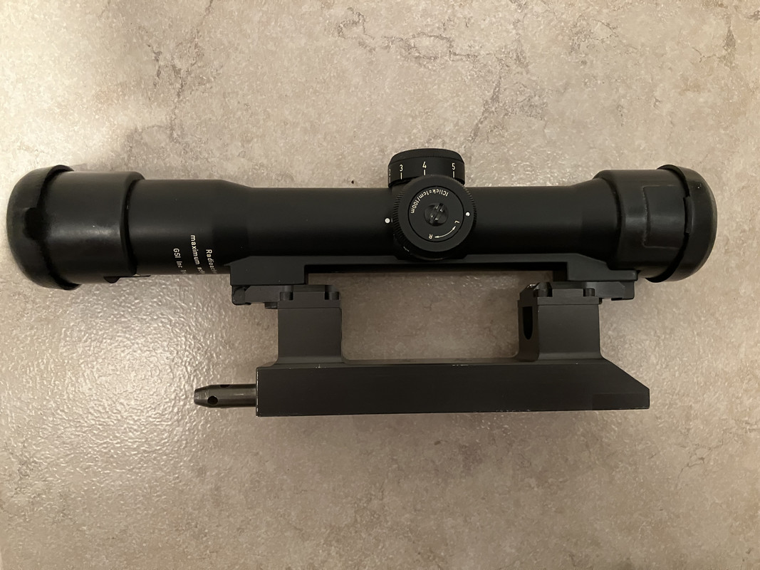
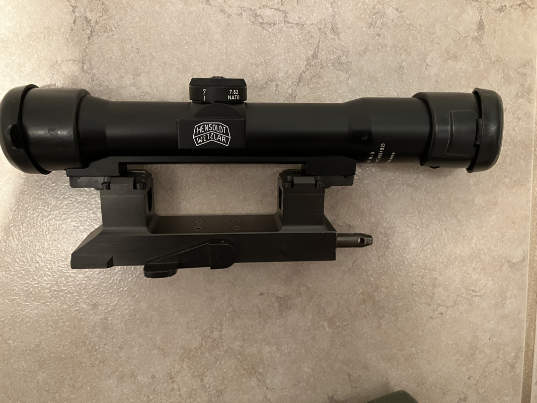
It fits nicely into a German military G3 scope case.


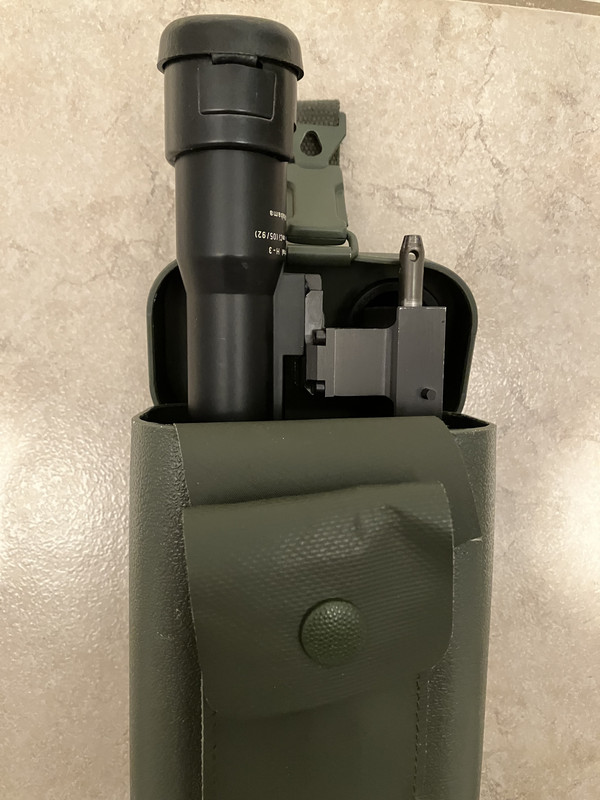
I'm also impressed with the radioactive material warning.


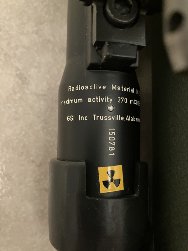
Now for what I need help with; how do I move the elevation and lateral drums when I get the scope zeroed in. I assumed this was identical to a regular Hensoldt Fero Z24 scope. But no, that's not the case.  I'm not going to mess with anything until I find instructions on how to do it. I've asked around for a BLITS scope instruction manual, but I've never found one. I saw that GSI (Gun South) is shown with the radioactive warning. So, I decided to contact them for some instructions. Then I found out that GSI has gone out of business. Damn! So now I hope I can find somebody here who can help me.

Here is my AMT with the BLITS/Estes Adams scope and mount attached:


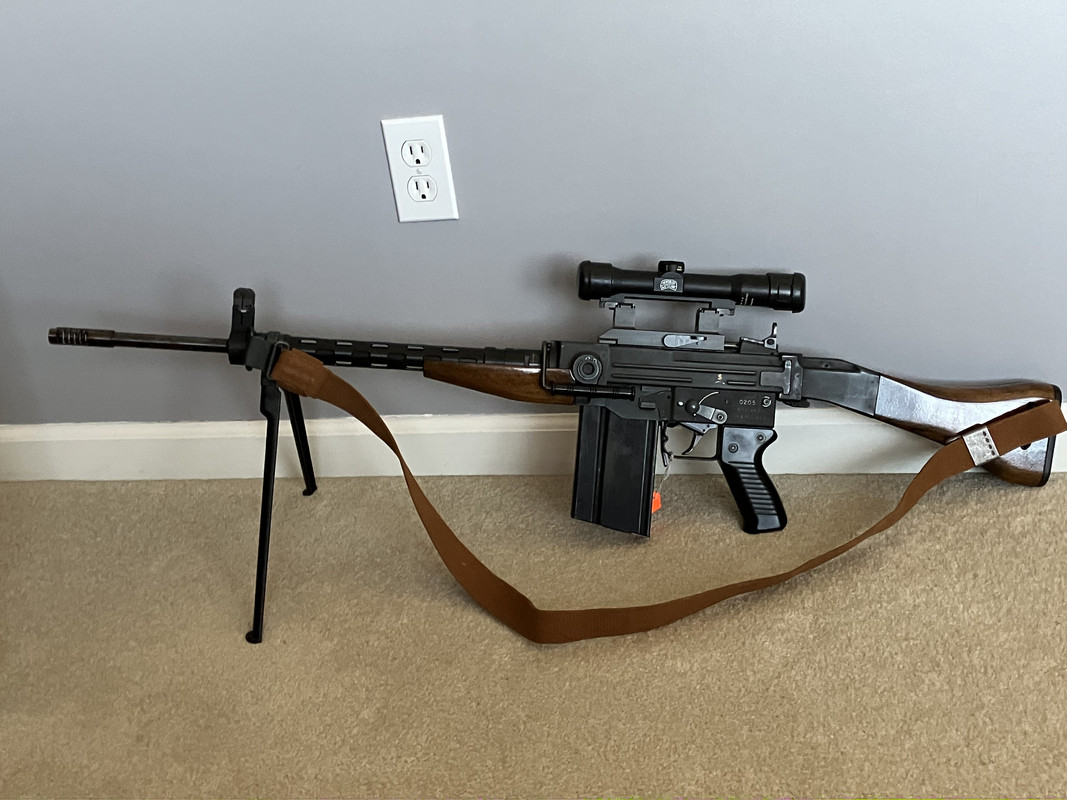
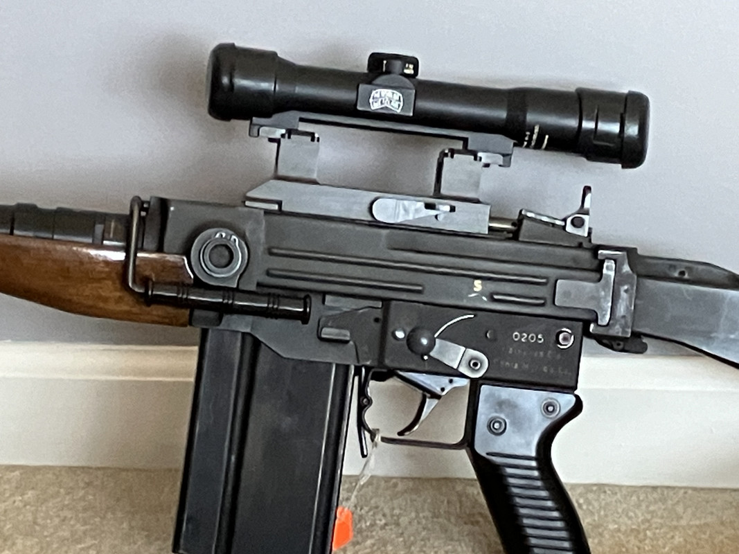
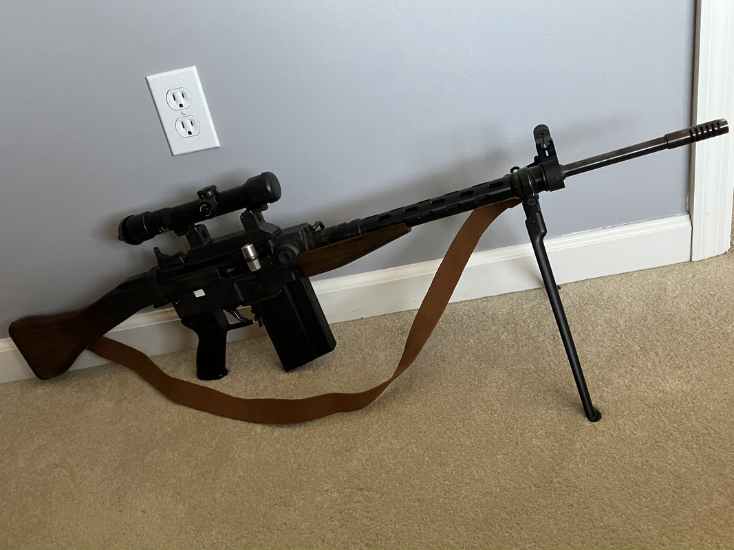
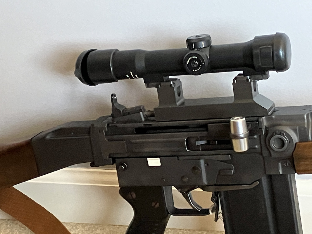
I emailed Hensoldt inquiring about a acquiring BLITS manual.  As for Hensoldt, I just struck out.  Here is their last email:

Dear Daniel,

many thanks for your email and your request.

The 4x24 BLITS rifle scope was last manufactured and delivered over 35 years ago.
Unfortunately, for this reason we no longer have any documents available.
We´re very sorry, but we can no longer help you with a manual.

Mit freundlichen Grüßen / with best regards

Frank Topp

Senior Bid and Program Manager Sights

HENSOLDT

HENSOLDT Optronics GmbH
Gloelstraße 3-5
DE 35576 Wetzlar
T +49 (0) 6441 4488 190
F + 49 (0) 6441 4488 186
M +49 (0) 171 5324775
mailto: [email protected]

www.hensoldt.net
Link Posted: 3/8/2024 11:44:54 PM EDT
[#33]
Discussion ForumsJump to Quoted PostQuote History
Originally Posted By mew:
I have enjoyed your posting from way back and have it bookmarked for posterity. The most important essay on the AMT ever made and I commend you for your perfect assessment of this beautiful rifle. I too have an AMT one of the last imports from Sig in Tysons Corner. CFI in Texas was the dealer I procured mine early 80's. Thank you sir for your attention to detail, it's truly phenominal!!!
https://i.postimg.cc/mtZsH3DG/AMT.jpg
View Quote


I wish this forum had a like button.  Thank you VERY much for your kind words.  I put a lot of work into these writeups and it's nice to know that they are helpful to people!
Close Join Our Mail List to Stay Up To Date! Win a FREE Membership!

Sign up for the ARFCOM weekly newsletter and be entered to win a free ARFCOM membership. One new winner* is announced every week!

You will receive an email every Friday morning featuring the latest chatter from the hottest topics, breaking news surrounding legislation, as well as exclusive deals only available to ARFCOM email subscribers.


By signing up you agree to our User Agreement. *Must have a registered ARFCOM account to win.
Top Top