CA, USA
|
Posted: 12/24/2023 2:40:46 AM EDT
Alright, I've hit a couple milestones in the same year (age and tenure at work) and have decided to mark the occasion with a bit of a personal project that is a little outside my exact area of expertise.
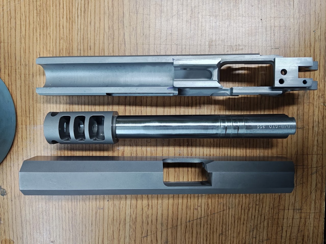
I've decided to build up two 2011s. One is a lighter weight commander, and one heavyweight government built like an open competition gun (though I currently don't have plans to compete with it, and will be loading both in 9mm minor) The components between the two will be basically the same, and the overall design will be shared so they look kind of like a matched pair. Obvious differences will be a heavier but clean trigger press for the commander, but a competition grade and very light trigger in the government. I have built up several 1911s in the past, am a 1911 and Staccato/STI/2011 armorer. I'm familiar to both platforms, but so far have only built up 1911s, not 2011s. Luckily, most of the tools transfer across both platforms. Parts were sourced this summer and fall. Here they are: 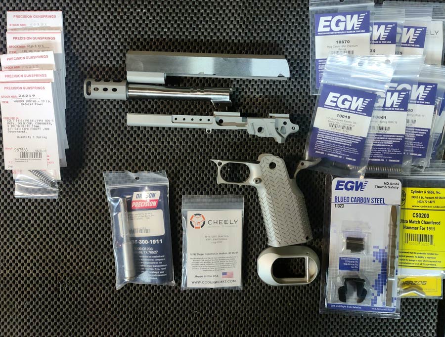 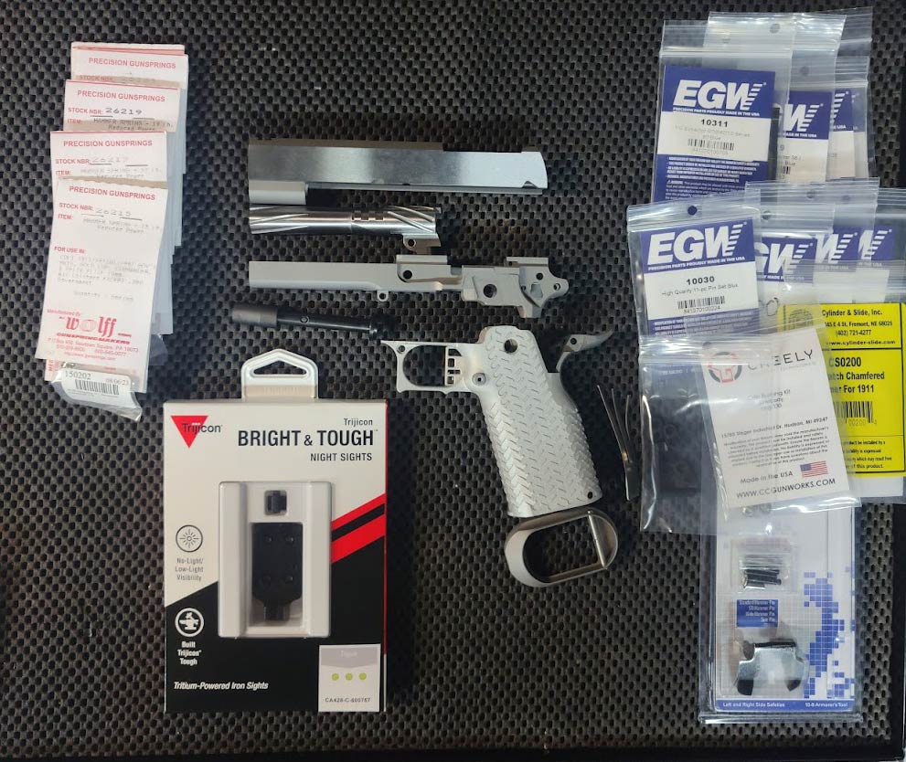 Frames are Cheely. Slides are Caspian. Grips are Cheely. Most all of the internals are EGW, except the hammers are Cylinder & Slide. Barsto barrel for the Government, and Fusion Firearms for the commander barrel. Here is the design inspiration (like the serrations and lightening cuts):  Work has commenced after locating a mill to get some time on, and I'll try to document the progress though I keep finding myself doing work and getting so wrapped up into it that I forget to take pictures of the milestones. This is not intended to be a how-to or a gospel of the ways of putting together a 2011 or 1911 of your own, but if it helps inspire you to get off the bench for that pistol project you have been itching to try, than that's a success to me. |
|
|
|
[#1]
This should be a great build so I'm in. Y'all are going to start costing me more money I see already. :)
|
|
|
|
HI, USA
|
[#2]
That’s an impressive pile of parts👍
The one caution I’d advise is be careful of your lightening cuts, I’ve seen many slides with impressive looking cut that cracked On your open gun slide I wouldn’t go lighter than 10.5oz I got a question on your caspian commander slide, did it come milled for the optic? |
|
|
FM, USA
|
[#3]
Nice. Is the frame of commander aluminum also? I assume so since you said lightweight build.
|
|
|
CA, USA
|
[#4]
Is the frame on the commander aluminum? No, it is carbon steel. The grips are aluminum.
Slide lightening - thanks for the advice. The overall design is from cheely, back when they accepted custom builds. I'm undecided on the final design yet, keeping overall weight in mind and trying to not get too aggressive. Did the Caspian come with the red dot cut? Yes, it is a factory option that they just don't have advertised. It fits the Trijicon RMR adapter plate (pictured.) |
|
|
HI, USA
|
[#5]
Thanks the info, I was wondering when caspian would start offering that as an option, how much did they charge for the cut
|
|
|
CA, USA
|
[#6]
The anticipated steps for the builds are:
Parts intake Base measurements and comparison Slide/frame fitment Barrel/slide fitment Barrel/slide/frame fitment Fire controls fitment Testing Slide cuts Testing Refinishing Testing Done We're currently sitting at slide/frame fitment. Some tools: 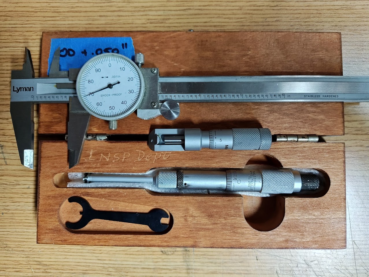 Analog dial caliper (good for general measurements) Can micrometer (good for outside rail measurements) Groove micrometer (good for inside rail measurements, ok for outside rail measurements) If you don't have a good second hand tool market in the area or generous machinist friends you can borrow from, eBay is an excellent source to get some used tools at a good price. The entire build probably could have been done with just the dial caliper but I wanted a more repeatable way to measure which took more of the human error out of it. 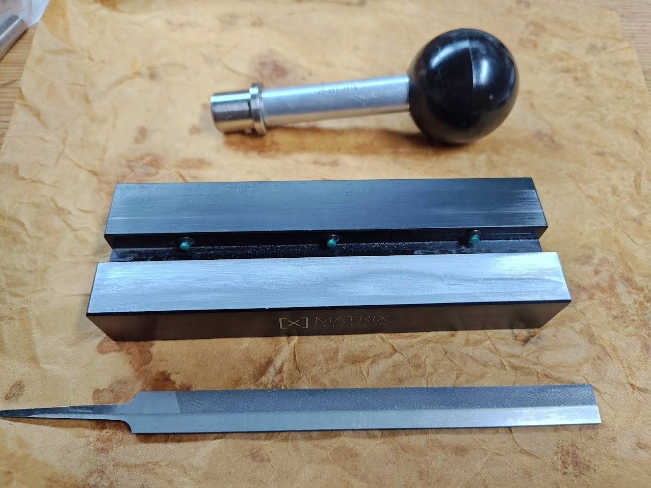 Handle for adding purchase to a slide. I only use it for the hand-lapping portion of the build to help prevent over-doing it and causing galling. Matrix Precision stoning fixture holder. I used this for dressing the underside of the slides and the sides of the frame rails. 1911 frame file. Used for some burr cleanup from the milling process. Previously used on other 1911 projects but I tried to avoid it for this one to make the material removal slowed and more deliberate. 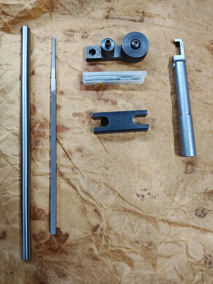 Barrel alignment gauge Barrel lug file Barrel alignment gauge (Nowlin) Lower barrel lug cutter Barrel holding tool There's also a Matrix Precision fixture for holding the frame in place in the mill vise, which was also useful on the bench while fitting the slide to the frame. The government frame did not fit in the fixture because of how wide it was, but the dust cover meant there were good parallel surfaces for holding. The slides were easy enough to hold with some gauging into plane. |
|
|
CA, USA
|
[#7]
Originally Posted By supercomp: Thanks the info, I was wondering when caspian would start offering that as an option, how much did they charge for the cut 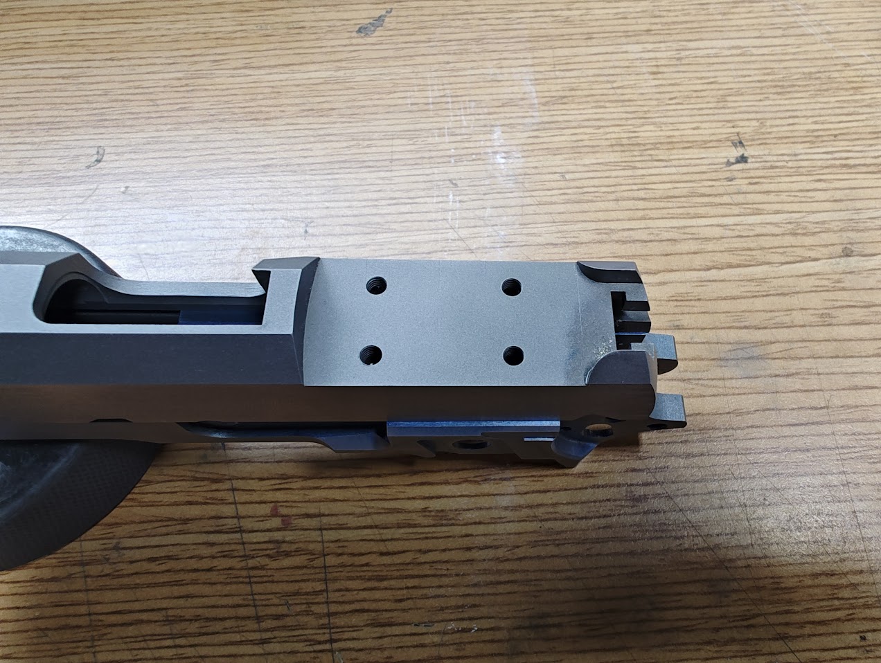 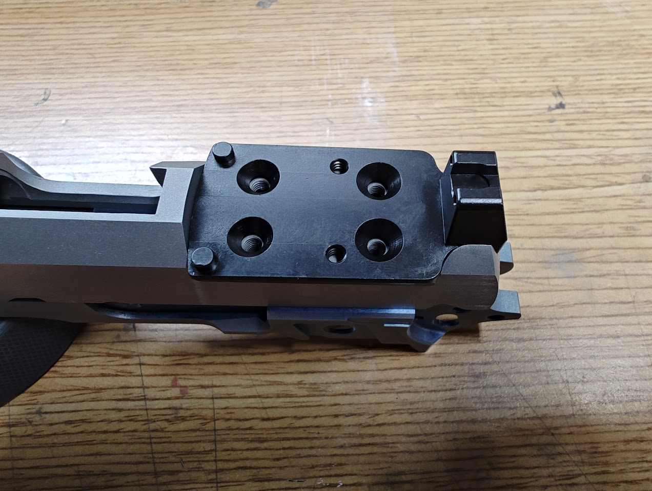 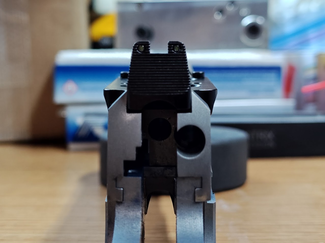 The cut cost $65 and you have to ask for it specifically since it's not listed. They will only cut for this mount (at least when I ordered) The mount has a little play in it, which I was not expecting. I haven't measured it, but it's a few thousandths. |
|
|
CA, USA
|
[Last Edit: leelaw]
[#8]
Measurements:
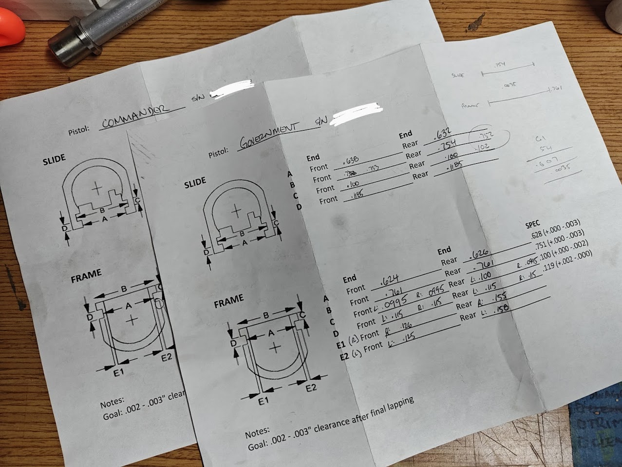 Measurements taken for critical fit, and to check for being centered. I measure at the front and rear of the slide to check for deviations that might need attention or could throw off measurements taken when mounted to a vise (so they can be accounted for and worked around) Slide/Frame Fitting: 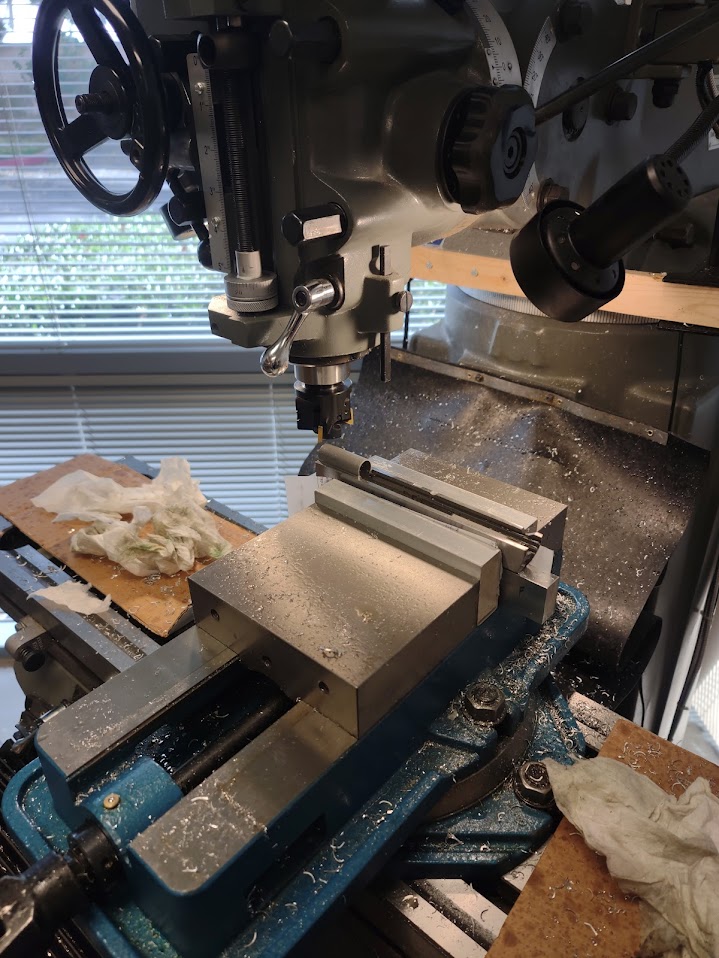 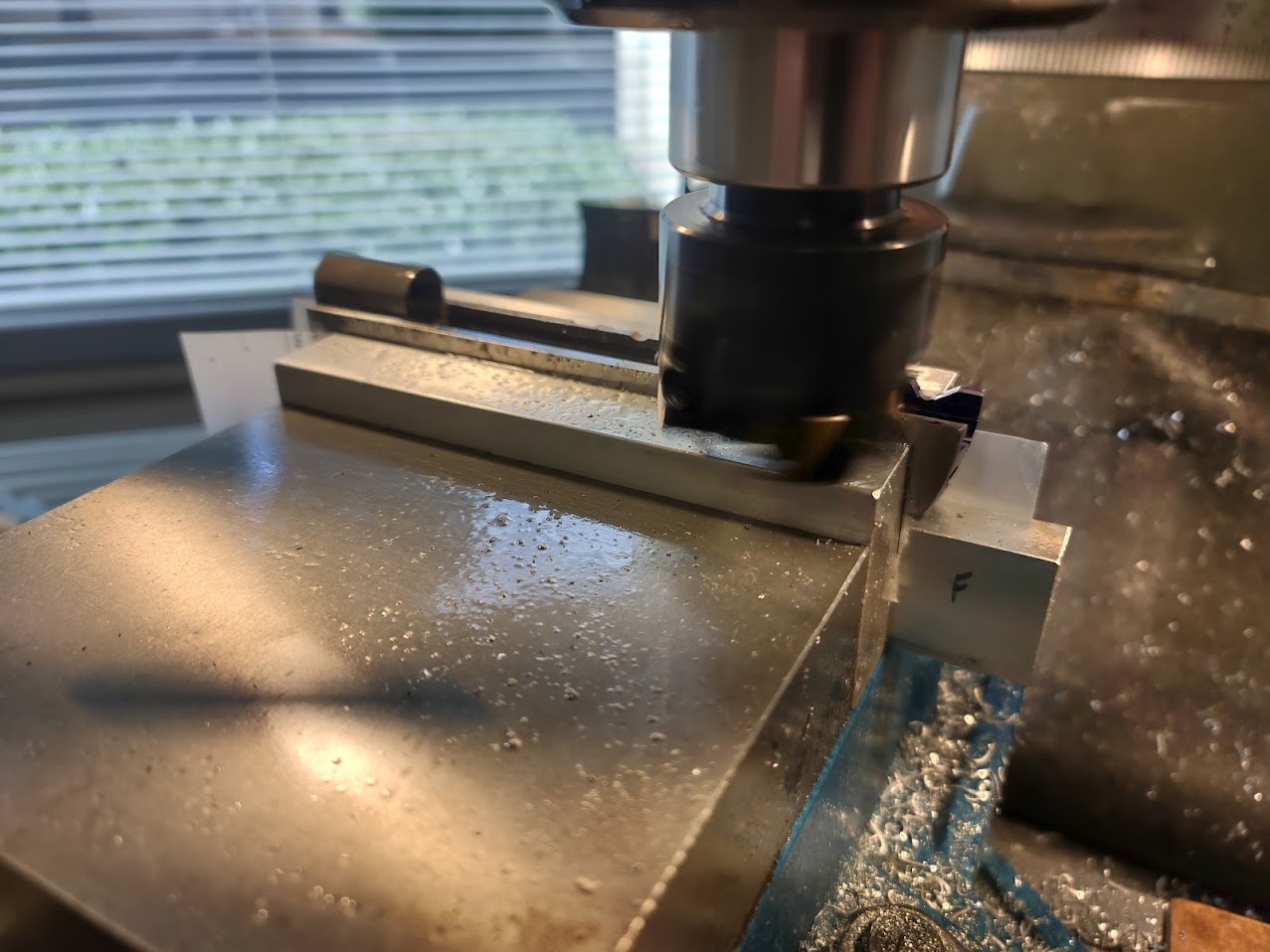 Using a mill and flycutter, I took off the bottoms of the slide and sides of the frame rails to within .001" of where they needed to be. I did this in two steps to crawl to final measurements, but with the small amount of material that needed to be removed it could have probably been done in one pass. Also, it wasn't my mill and it was a bit of a learning experience for me. "Measure twice, cut once" turned into something closer to "measure four times, cut once, re-measure and cut again." The machine finish was very nice in the end, and a few passes with 400 grit stones almost completely removed the machine marks.  The only tool I used for easing the slide on and off the frame during fitting. If you use a hammer, you'll likely enter into galling territory quickly. Using a Matrix stoning jig and progressively finer stones (though primarily just 400, 600 and 800 grit) the bottoms of the slides and sides of the rails are dressed until they begin to fit, then they're marked (I used dykem, prussian blue, and blue Sharpie, with the most consistent results coming from the Sharpie), fitted together, the points of contact are noted and re-dressed. Repeat. Repeat again. And again. Eventually the slides will cycle fully on the rails, but be too tight to function as a firearm. The stones are cleaned often and kept lubricated with WD-40 and honing oil. Fitting the two slides and frames was between 6-8 hours for this step, largely because of the grit of stone chosen. It could have been sped up by starting with 220 grit, but I didn't want to over-shoot a measurement while trying to progressively increase grit to remove prior grit markings. By cutting to your final dimension or using lower grit stones or files sooner, will speed up this step. For this project, I wanted to go slow and deliberately so it cost me time. 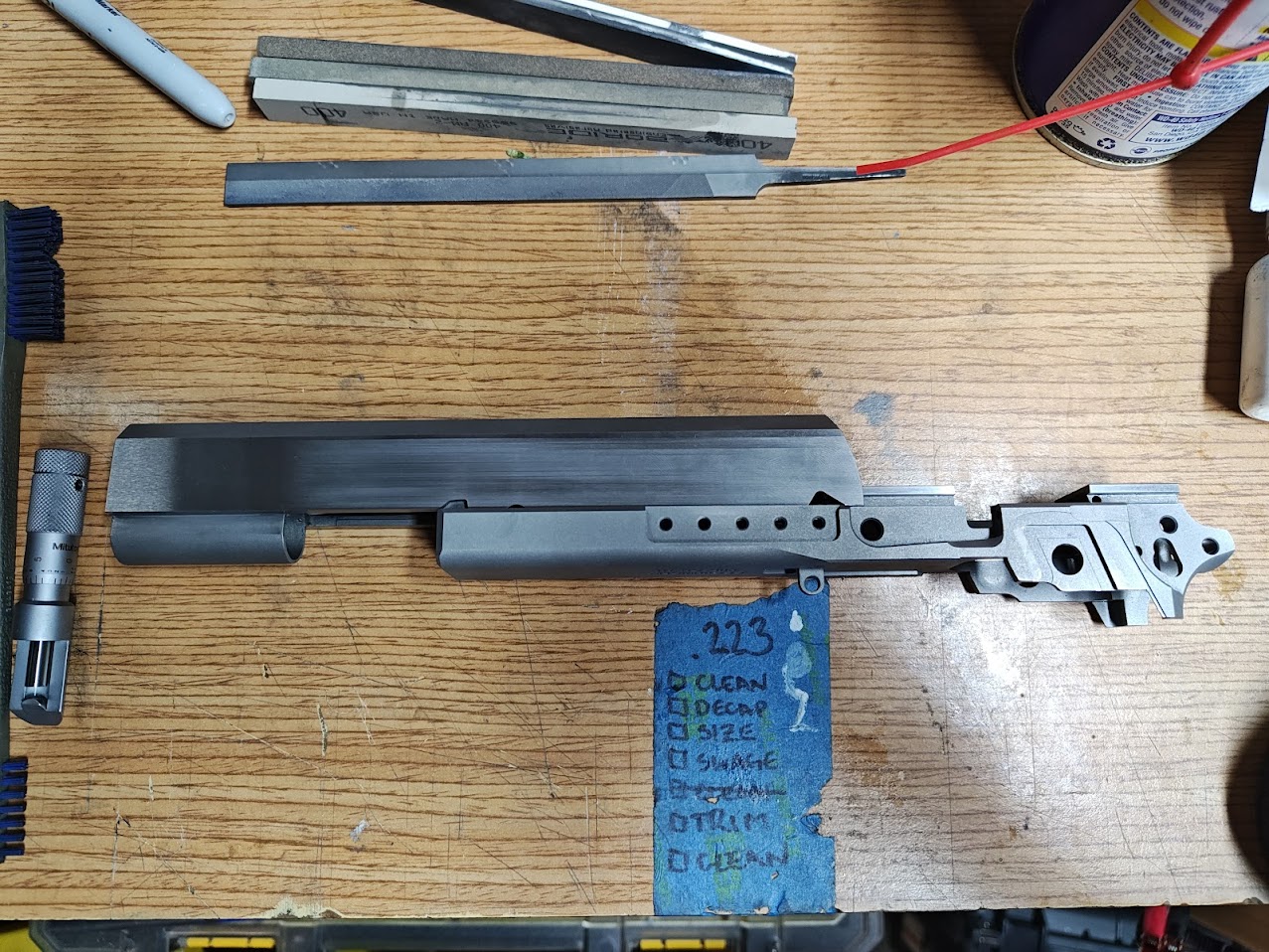 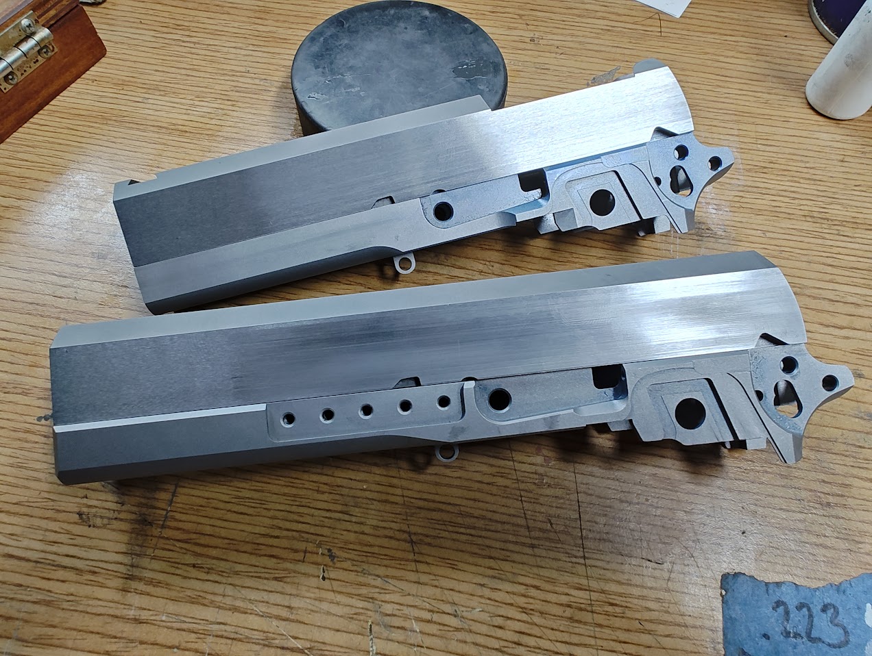 At that point, I used some Amazon Chinesium (I assume, the company is based out of California and shipped from there, but who knows these days) 100,000 grit diamond paste diluted with honing oil. Using a cotton swab, the mixture is put on the surfaces which are in interference and lapped back and forth until they glide by each other. This does open up the fit between the slide and frame but it still feels remarkably tight so I'll keep it at this point unless testing shows it to be a problem. 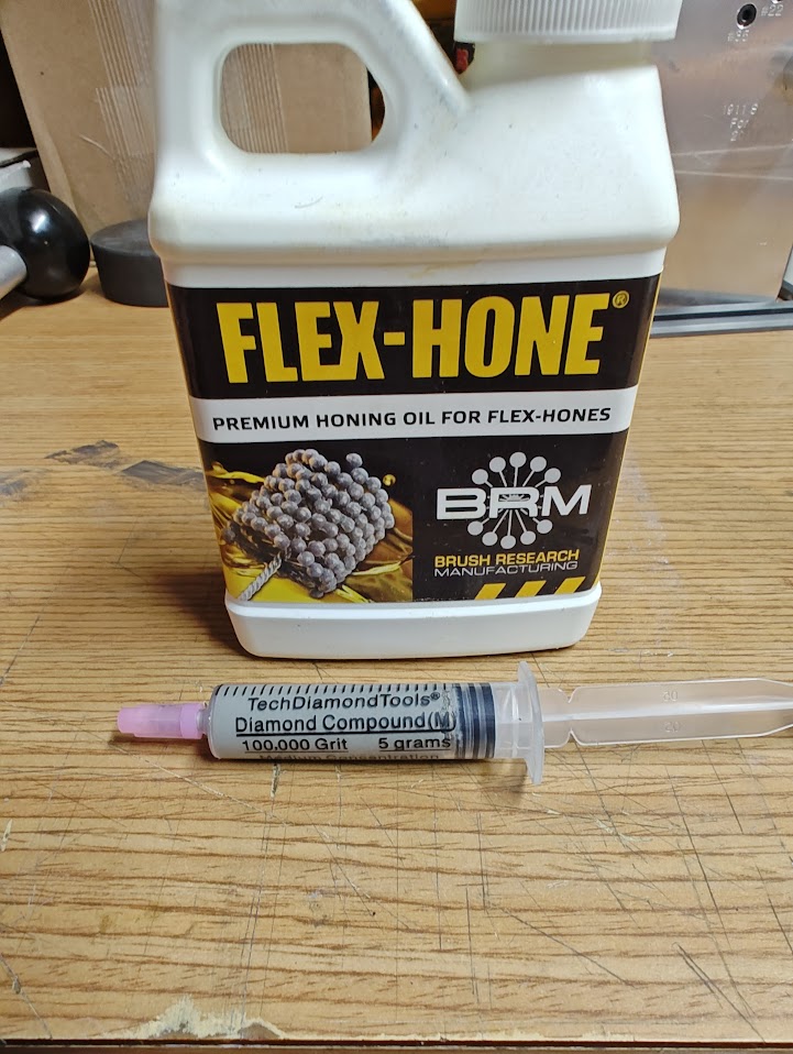 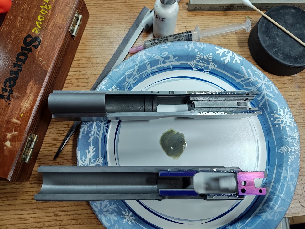 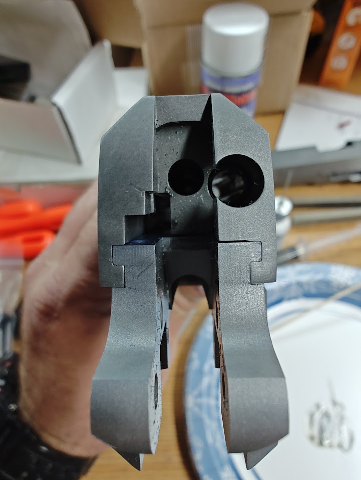
|
|
|
|
[#9]
Nice build, following for updates.
|
|
|
|
|
[#10]
Very nice OST.
|
|
|
|
IN, USA
|
[#11]
This is really cool. I always wanted a cheely grip for my staccatos. Following this thread.
|
|
|
CA, USA
|
[#12]
Originally Posted By sheepdog697: This is really cool. I always wanted a cheely grip for my staccatos. Following this thread. Here's a mockup of the Cheely grip on an STI (the parts that matter are dimensionally the same between the STI and Staccato frames) These are the Cheely E2 grips in the non-aggressive texture. The E2 style is designed for a pinned grip safety and the backstrap is not flat like a traditional 2011, but has a profile like a CZ75. The non-aggressive texture is still very grippy and would not be forgiving to drawing from a holster with an improper grip - changing the grip mid draw would be challenging. I might have the edges rounded or beadblasted ever slightly before finishing. The undercut for the trigger guard is quite nice, but after some testing I might remove the finger groove closest to the trigger and make it flat for the entire run. 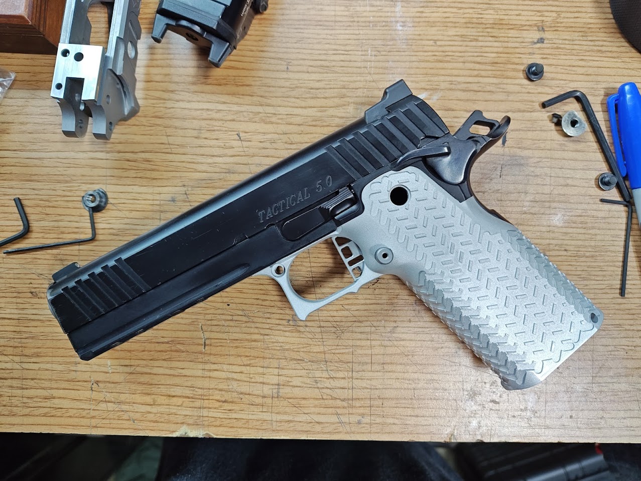 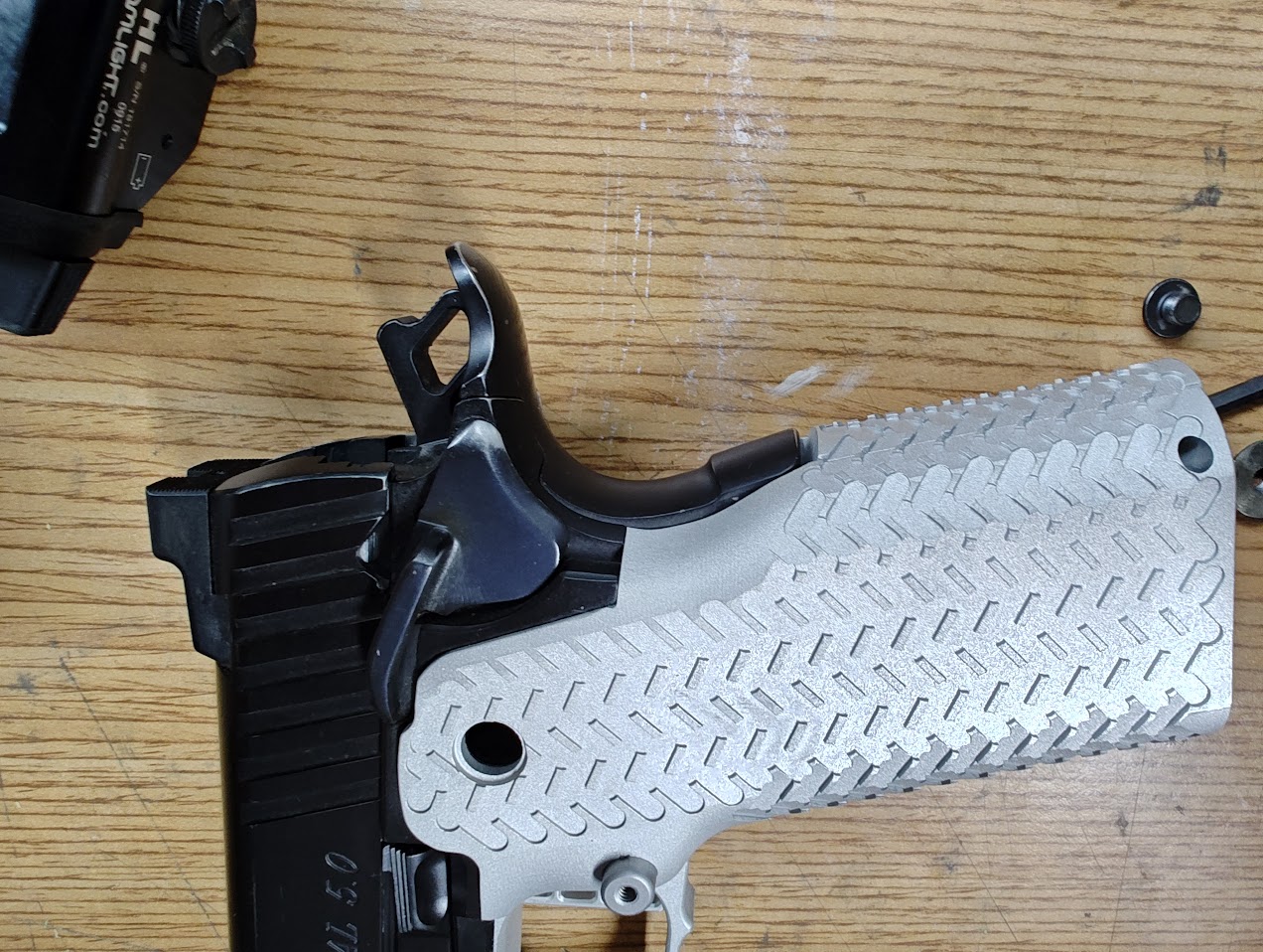 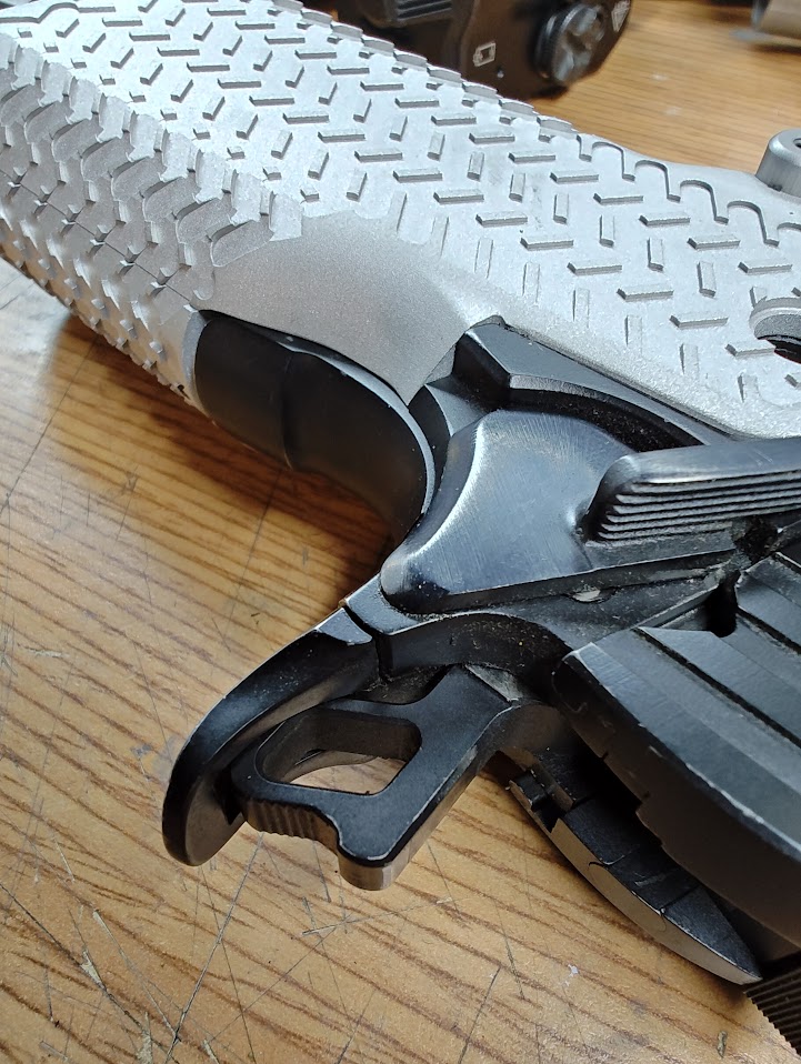 Traditional 2011s have this little step in the frame just below the frame safety. The Cheely grip is designed for the Cheely frame, which has this are radiused. Because of that, there is a little shelf caused by the grip. The STI/Staccato grips have the profile of the step tapered into the the grip. I've always found that little step to be irritating on my right thumb after prolonged shooting, but if I were to install a Cheely grip on an STI/Staccato frame I'd have to blend in that shelf on the grip a little, or at least remove the sharp edge. The Cheely grip safety that comes with the E2 grip is an almost flawless fit to the grip and rear profile of the frame. Minor fitting would be needed. |
|
|
AR, USA
|
[#13]
Looking GREAT Lee, Congrats.
So what did you think of the lapping compound? would you do it that way again ? Larry |
|
|
CA, USA
|
[#14]
Originally Posted By Larrys1911: Looking GREAT Lee, Congrats. So what did you think of the lapping compound? would you do it that way again ? Larry I certainly would. I had some concerns that the diamond might embed into the steel and persist, but it doesn't look like it happened. The action is silky smooth and tight, maybe still too tight. Once everything is together and testing begins I'll know whether some things need to be opened up. Made some progress on the barrels this past week, will post some more soon. Also made one small design change. The sears will have a true radius cut on them, instead of a traditional. Wanted to try that for the first time. |
|
|
CA, USA
|
[#15]
The barrels are in the works. Some more milling is needed for the government (cutting down the muzzle and putting a slight angle on it). The Brazos Custom Build Your Own Gun writeups have been particularly helpful in regards to the one piece barrel-with-compensator since there isn't a whole lot of information out there and the slight angle on the muzzle honestly completely escaped me during pre-planning. Though I guess the same effect could be had by cutting the rear of the compensator, I'll trust the professional opinion on this one.
Both triggers needed some work in order to fit onto the grips properly. The trigger in the aluminum grip needed the width of the grip opened up.  There are several small areas in the corners that Cheely has left oversized so that they can be fitted to the width of the trigger. 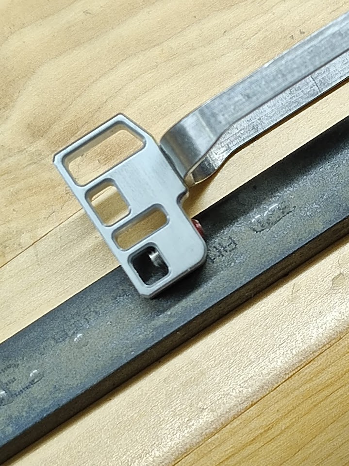 For the steel grip, the width was already perfect, but the trigger shoe was too tall. Several passes on a 320 grit stone on the top and bottom quickly fitted the trigger to the opening. 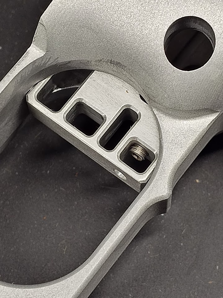 After the triggers were both close to fitting into the grips, I used 600 and 800 grit stones to smooth over any touching surfaces on the grip. The result is a smooth trigger pull without any snags. The frame safeties were next to contour. They shouldn't be fitted to the sear until the work on the sear is completed. I'm going to give the True Radius a try on both sears, so while I did practice a little with the stones on the primary sear angle, the True Radius fixture is still in the mail. The safeties are EGW HD. The contour of the safety is my preferred style (as opposed to the Springfield Armory, Les Baer, Wilson Combat, etc. which are much more curved and pointed) but there is an interference issue with the frame at the bottom. 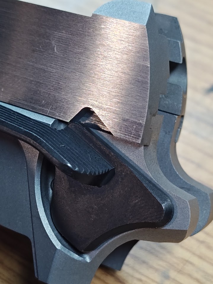 The slide interference issue aside, the bottom of the safety is contacting the frame. 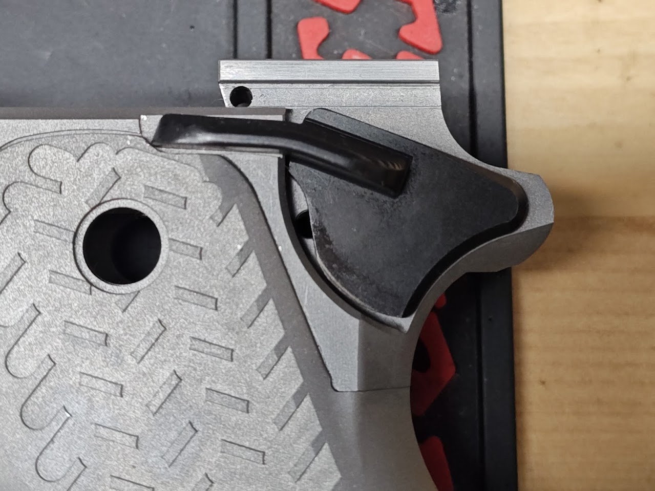 I used the smallest diameter brass punch I had to scribe a line across the bottom of the safety parallel with the frame, then used a fine grit belt sander to slowly walk the edge up to the line. A little bit of stoning on the edges to remove the burr and it looks like this. 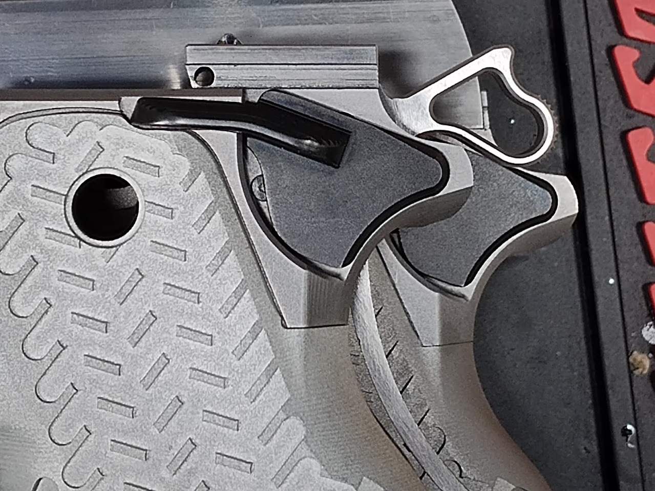 Before (background) and after (foreground) |
|
|
CA, USA
|
[#16]
Had some time today to do a little detail work. Both firing pin retaining plates were fitted. The Commander just needed the sides taken off a little bit at a time (first filing to get within a thousandth, then stones to bring in the last little bit). The Government needed both the sides taken in, plus a little radius work at the top edges of the plate to fit well into the corresponding cuts in the slide.
After the plates were fitted to the slide, then I fit them to the extractor. In both cases, the corresponding groove in the extractor just needed to be opened a little to fit the slide. Using a gauge round against the hook of the extractor, I determined that the rear of the extractor should be filed off, instead of the front. The 1911 frame rail file took quick care of this very mild job. The Commander slide was cut out for a Trijicon RMR mount. The mount has a recess underneath the rear sight which will fit the firing pin retaining plate (if you have a full size one) 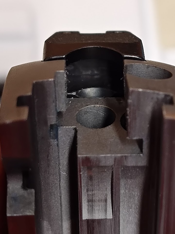 But.... there's a little dimensional variance here. 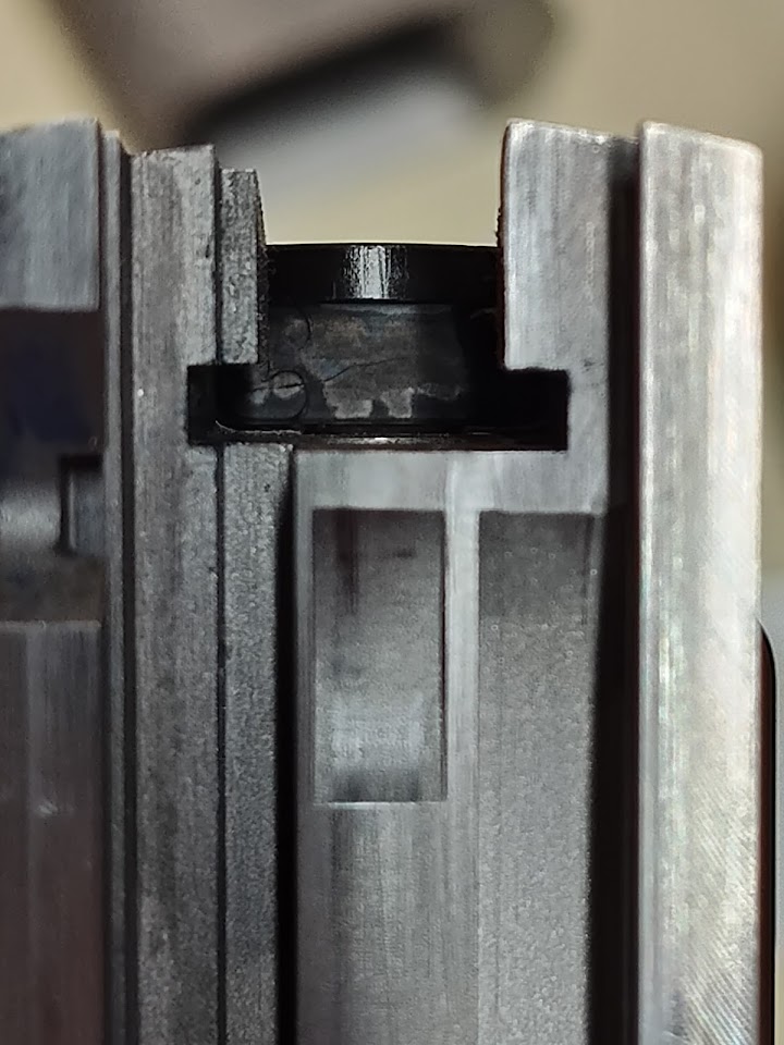 A little ledge of the mount that sticks proud of the forward face of the firing pin retaining plate. Dang it. For everything, I default to modifying the less expensive part first. In this case, it means the plate, and not the mount. 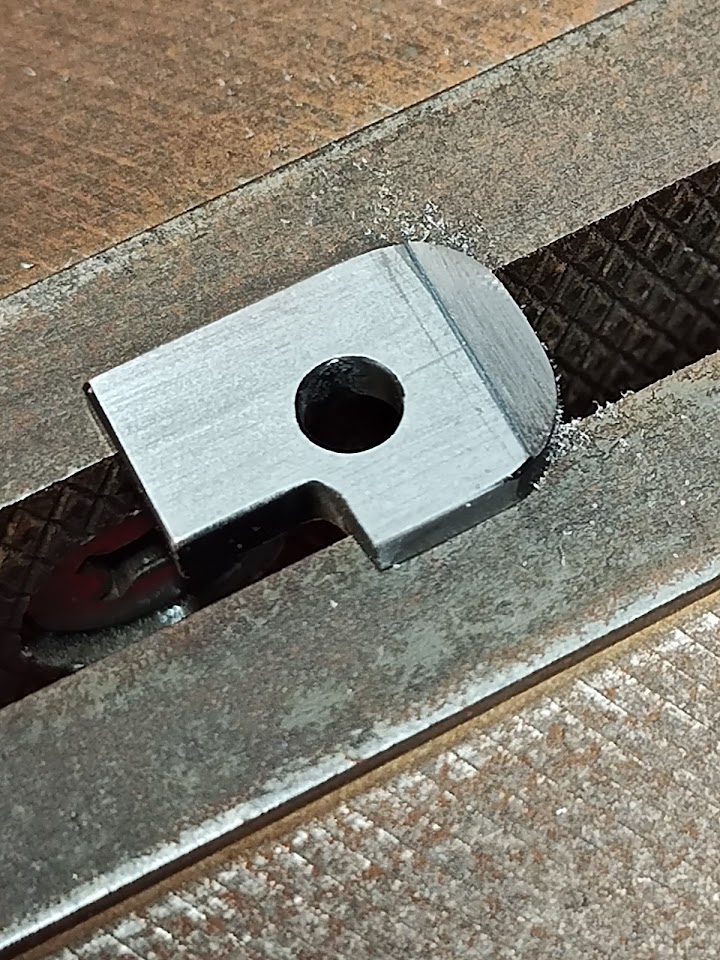 That's OK. Taking some measurements, I know how many thousandths I need to take off in order to accommodate that little offset. I install the plate, then scribe a cut line with a knife along the front face. Hand filing takes off the bulk of the material. 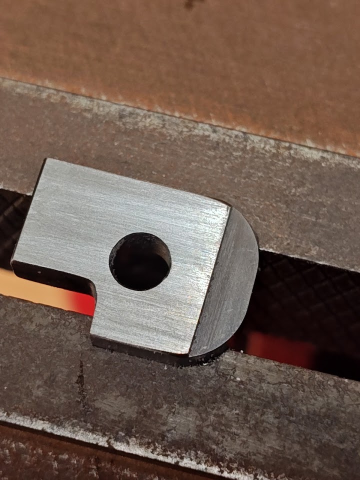 After a bunch of careful filing and stoning it looks great and fits well. ....except that little ledge actually interrupts reinstalling the firing pin. At the end of the day, I ended up cutting the entire firing pin retaining plate short instead.  |
|
|
CA, USA
|
[Last Edit: leelaw]
[#17]
Lets fit some barrels, starting with the government.
 The government barrel is a single piece barrel and compensator made by Bar-Sto. It is oversized is several dimensions: front of the barrel (other than the last 1/4" which is perfect to the slide), bottom lugs, sides of the top lugs, hood (length and width), and the chamber is cut short for final reaming once the barrel is fully fitted. In retrospect, it's the most time consuming barrel fitting that I've done, especially with removal of material from the top and sides of the barrel towards the muzzle. On top of that, the front of the slide needed to be angled slightly to accommodate the lift of the rear of the barrel during lock-up (something I had not previously considered.) I took measurements for the slide from the muzzle to the first locking lug, and the barrel from the rear of the compensator to the first locking lug. Using some math, I figured that I needed to remove .014", then add a .003" to .005" clearance to the muzzle. In total, I removed .017", intending to stone away any little additional amount needed. Well, let's get on with it: 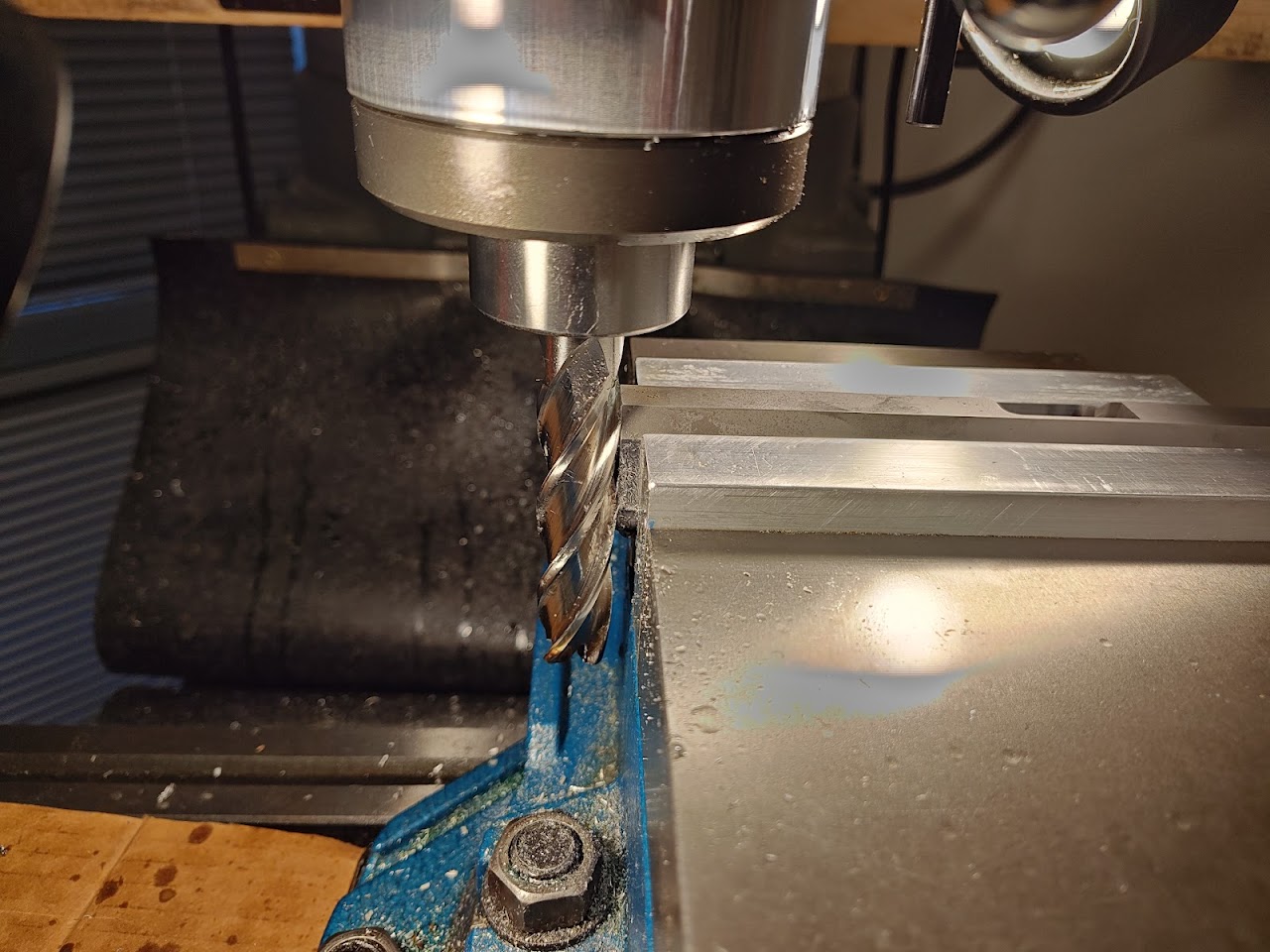 The bottom of the slide rails run perpendicular to the face of the muzzle. In order to put a .5 to .75 degree angle on the muzzle (more material removed from the bottom of the slide than the top) I measure the width of the parallels that the slide rails stand on, then use trigonometry to figure out how much elevation to give the muzzle of the slide. Using shims, I raise the muzzle the calculated amount, then crank the vise closed. Had I remembered my digital angle finder I would have re-checked this, but I did not. Trust the math. Let the mill fly! 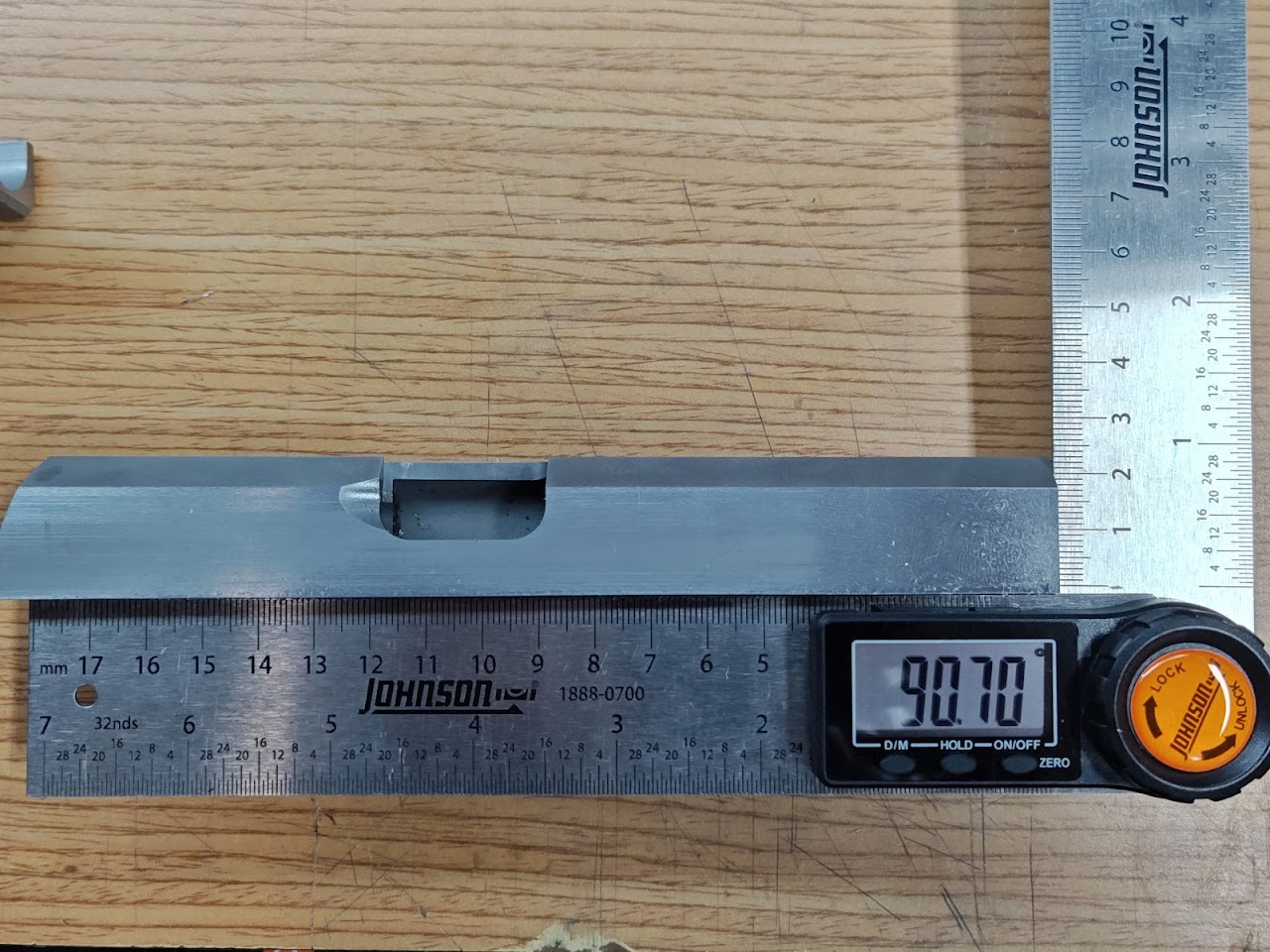 Was aiming for .66 degrees. I'm pleased with this. 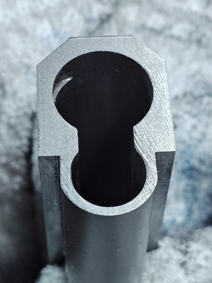 Muzzle, after the mill cut (there was a little chatter) 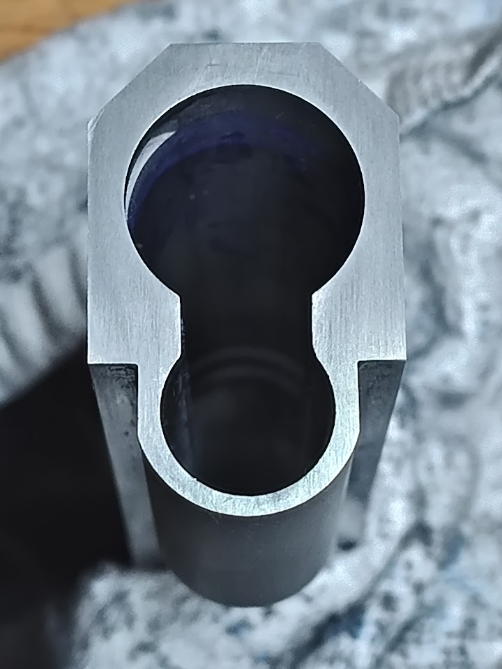 Cleaned and stoned. 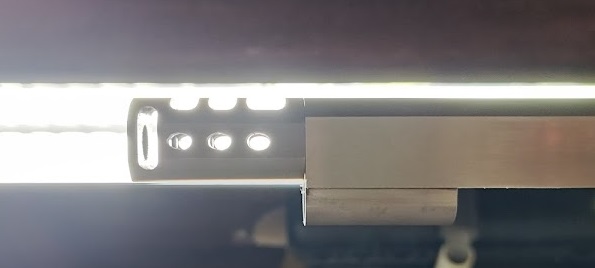 After fitting the hood to final length (below) and a lot of work forward of the lugs for fitment, here's how the clearance at the muzzle turned out. Let's fit the hood: 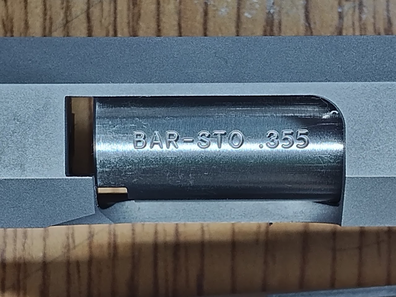 The hood is too long and too wide. 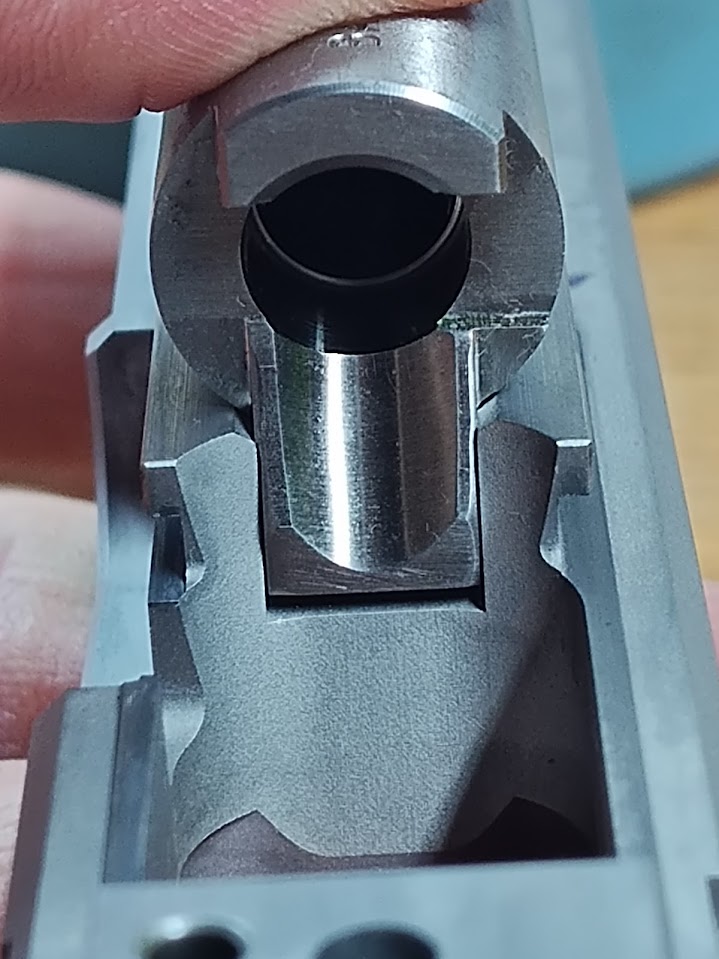 The vertical impact surface (VIS) hits appropriately on the frame. The horizontal at the bottom of the barrel impacts the frame, but the bottom of the ramp does not. From my reading, this is acceptable to a degree but I'll test some more and adjust fitment later after being able to assemble the slide and barrel assembly onto the frame (foreshadowing 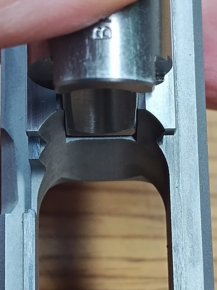 Without taking material off the VIS, this will not move more rearward. It is preferred to have the ramp slightly forward of the frame for an unramped barrel, but for a clark/para ramped barrel things may be different. The ramp is so deep that it ends well below any surface that the nose of a round might impact. The 2011 magazines also have good clearance from the ramp if it is a little pronounced into the frame (foreshadowing) so this will be tested well after the fitting is done. 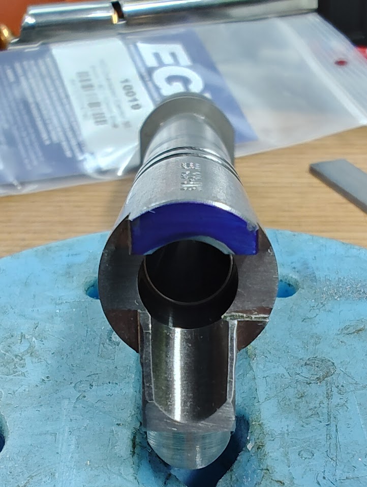 I put the bottom lugs of the barrel into a fixture to keep it aligned upright and centered in the slide. Take some measurements for the left and right side of the hood, then slowly file down the sides. When I'm close, I mark the sides with blue sharpie, press the hood into place, find the areas of contact, then begin stoning away the small difference. This shows where the sides of the breech face impact the rear of the hood. 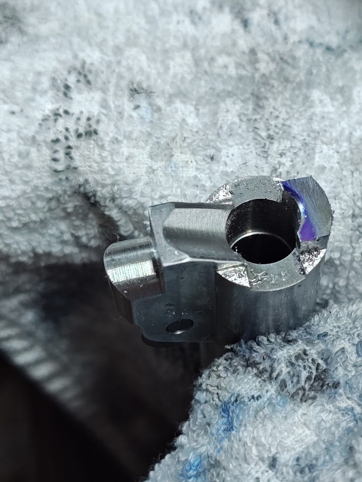 The operation for the hood length is similar. File it close, then repeatedly check with sharpie and slowly remove material with stones. The barrel can be installed to verify the lugs are at the correct depth to engage, but... there is a lot more fitting to do before it can actually lock into battery. |
|
|
AR, USA
|
[#18]
Hey Lee, AWESOME well done. Wouldnt have thought of the angle on the slide either since I have never done one.... You just make me want to buy a little Mill.
|
|
|
|
[#19]
Are you using Red Dirt triggers?
|
|
|
|
CA, USA
|
[Last Edit: leelaw]
[#20]
Originally Posted By Bradd_D: Are you using Red Dirt triggers? Good eyes. Yes, Red Dirt flat, Cheely frame profile triggers. |
|
|
|
[#21]
Originally Posted By leelaw: Good eyes. Yes, Red Dirt flat, Cheely frame profile triggers. |
|
|
|
AR, USA
|
[Last Edit: Larrys1911]
[#22]
Originally Posted By Bradd_D: I recently put a Red Dirt in my Staccato. I need to figure out how to tighten up the play up and down. https://www.ar15.com/media/mediaFiles/2261/20240113_185634_jpg-3093783.JPG had a frame that was cut over size in the verticle trigger shoe area once, I carefully Peened the trigger shoe (Center punch several times - it raises the metal surface creating a kind of burr) itself on both top and bottom, wasnt pretty but it worked. Youll have to refit it probably and stay away from the edges or you can screw it up, IMO several center small punch hits work better than a few deep ones I work on the road and bought a Rock Island 10mm and the stock trigger shoe was steel and way undersized, since we had three day weekend and I was too far to drive home I had nothing to do and bought JB weld peened the up and down again (that wasnt enough) and put a very small amount of it on the shoe, it worked but its a PITA and JB weld is kinda sticky so if I was doing it on something i really Cared about I would use a different epoxy. I did this while waiting for a Wilson trigger to be delivered because I was bored, never had any intention of it staying in the gun, it was too heavy to start with and adding more weight was not helping. They make aluminum triggers for a reason. Trigger bounce IS a thing. I just wanted to see what I could do with it. If you are talking about the trigger track itself being too large for the bow take a small sharp center punch and dimple each corner on the top part (youre trying to create a raised area on the edge of the bow to take up space vertically) on the in each of the four corners, obviously you have to have some type of blocking inside the bow to do this. In all honesty I wouldnt do either of these unless I had no choice, They work fine and you cant tell unless you disassemble the gun and pull the trigger out but its SUCH A PITA to do when you can just buy a trigger that fits. Ok there is the quick and dirty methods. This is the one I would use if I just had to have a certain trigger that was too big or if the track was just cut too large. If you have a drill press and are good with your hands this is the method used by the pros and is definately prefered. you drill a hole or couple in the top and or bottom of the shoe just deep enough to hold a delrin rod (sorry dont remember the size off the top of my head) you drive the delrin rod in and trim it/them to fit.... Easy peezy :) Id MUCH rather have a gun that was on the small side of tolerances than the large side. |
|
|
|
[#23]
Originally Posted By Larrys1911: This is the one I would use if I just had to have a certain trigger that was too big. If you have a drill press and are good with your hands this is the method used by the pros and is definately prefered. you drill a hole or couple in the top and or bottom of the shoe just deep enough to hold a delrin rod (sorry dont remember the size off the top of my head) you drive the delrin rod in and trim it/them to fit.... Easy peezy :) Id MUCH rather have a gun that was on the small side of tolerances than the large side. |
|
|
|
CA, USA
|
[#24]
Originally Posted By Bradd_D: That's what I've been considering. With the trigger track being in the plastic grip, I don't want to do anything that will create drag by digging into the plastic, i.e. set screws, peening, etc. It's a much more time consuming proposition, but what about dovetailing a bit of brass (to extend the height of the trigger bow) into the steel of the bow, then filing, sanding and polishing that to size? It's still a harder material than the polymer, but would provide a much smoother surface than a peened edge. The bow on these are not as tall as the corresponding channel in the frame, but because the trigger shoes are so closely fitted and running smoothly, I don't feel much lift at all. Of course, more testing is needed. |
|
|
CA, USA
|
[Last Edit: leelaw]
[#25]
Government barrel first.
The commander was actually a lot easier to fit than expected (but had one weird quirk) than the government barrel was. The government barrel was oversized in many dimensions which needed some cleanup. 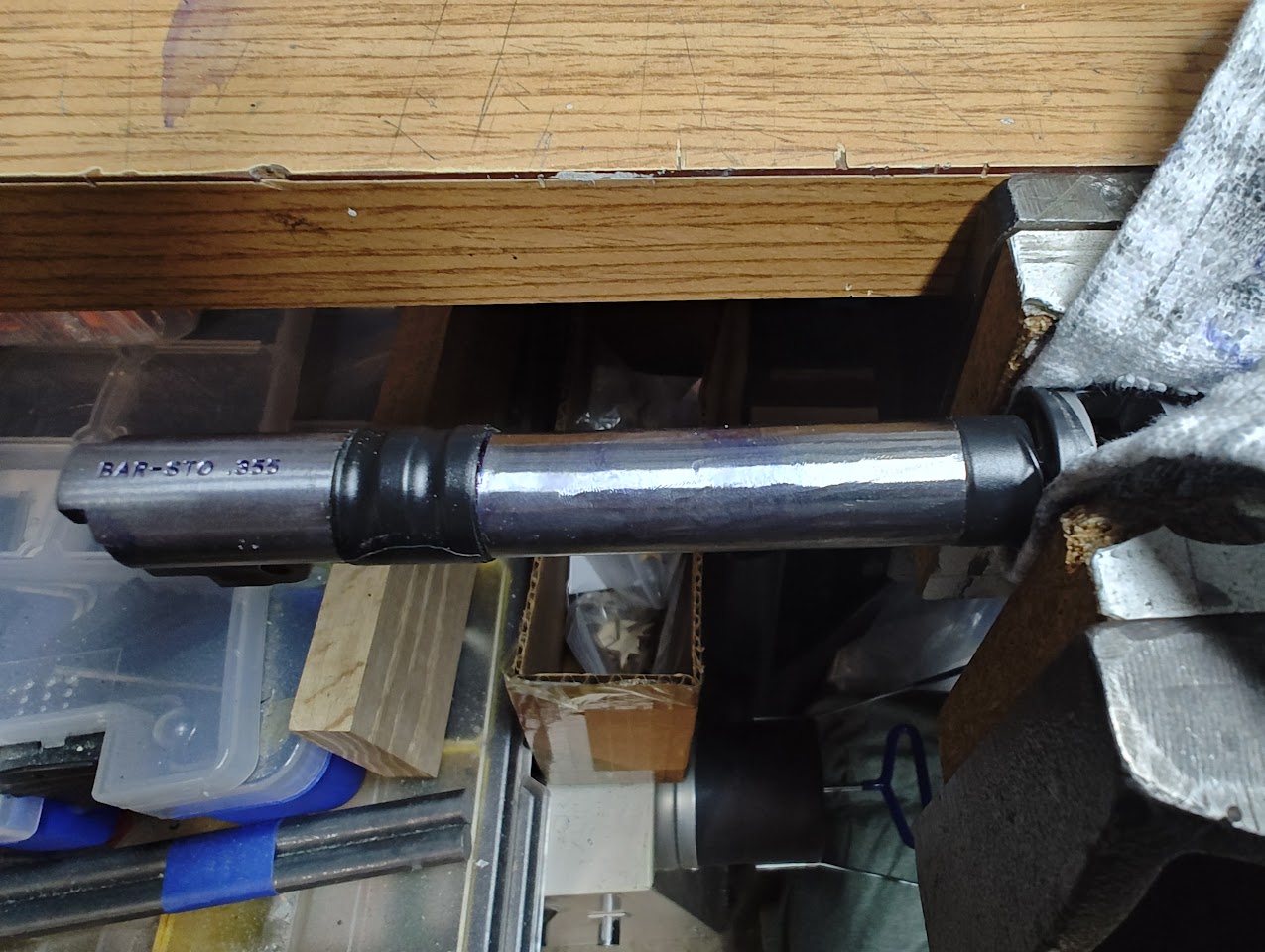 Ever looked at your 1911 bull barrel and thought "huh, there's this long section across the top that's milled differently than the rest, I wonder why that is?" Well, it's because the barrel binds with the slide when it tips up into full lock, causing the barrel to act as a spring. Everything between the front locking lug to just shy of the rear of the compensator needed filing to fit. Imagine the whole barrel coated in dykem and the interference slowly revealed, filed away, and repeated. This was about two hours work for this section. 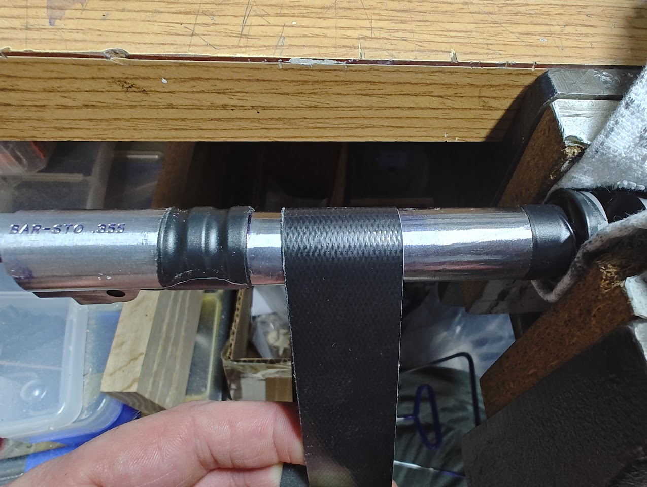 Well, once it's filed, it needs to be sanded.... but I need to mask off some areas to prevent rounding hard locking surfaces. 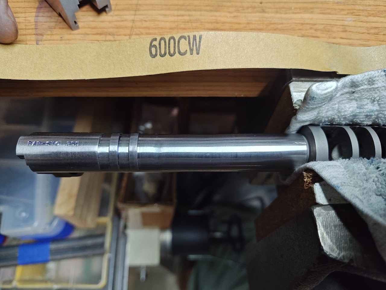 Mostly sanded (to 1200 grit). This will be cleaned up again after testing, but before refinishing.  The bottom of the barrel needs some fitment. Using the dial caliper, I can tell that my lockup is over the .045" specification when the barrel is in the slide but the frame is not involved, but once the slide fits on the frame the measurements go to heck. This area of the barrel (just above the lower locking lug/ramp area) needs to be shaved a couple thousandths. Now all measurements are good to go and the barrel swings freely out of the way. Taking some measurements, it looks like a #5 barrel link will work best for this barrel and frame mating, though the lower lug will need some cleanup way at the end of this.  Once the barrel has clearance from the slide, I check the Vertical Impact Surface (VIS) for interference. 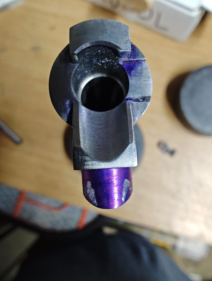 There isn't a lot of documentation on this, but from what I can tell (and after much stoning and some sanding) this will be an acceptable mating surface, which will allow for some break in over the testing process. I'll revisit this area during testing and evaluate whether the VIS mating surfaces moved, by how much, and whether further modifications are needed. 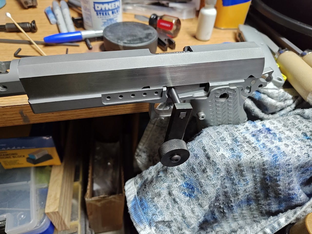 Let's cut some lower lugs. Just until the safety (not pictured) will fit into the corresponding cutout in the slide. 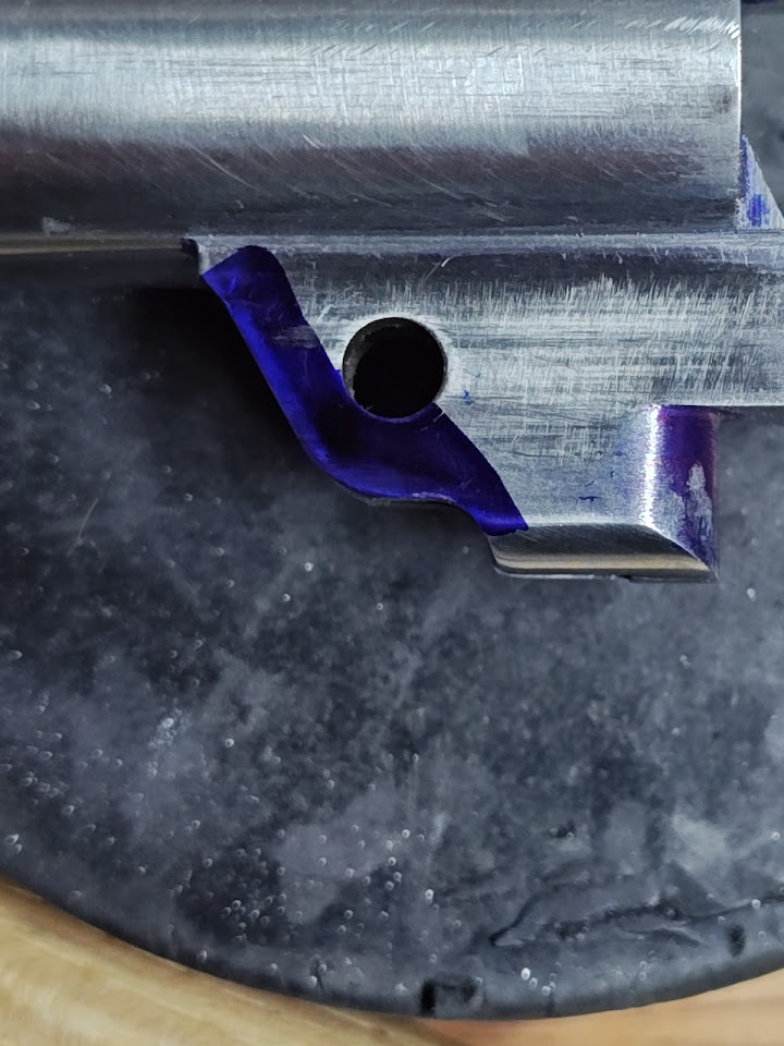 Once the lower lug is cut, I install the #5 link on the outside of the lug then scribe a line. There are a few thousandths that need to be cut back in order to fit. 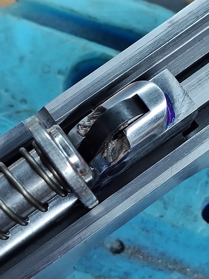 After a little filing, I use a donor #5 link and slide stop to hand-lap the last bit of the radius of the lower lug with 600 grit lapping compound. This is just to bed the slide stop into the lower lug. Once that's done, I confirm a good contact patch between the lower lug and the slide stop (with the real #5 link and slide stop in place.) |
|
|
|
[#26]
Really do appreciate the updates and the time taken to post all the work.
|
|
|
|
GA, USA
|
[#27]
This is an amazing thread! Thank you for sharing the details.
|
|
|
CA, USA
|
[Last Edit: leelaw]
[#28]
Of course an after-the-fact realization that I forgot to mention a step.
While fitting the barrel hood, it is imperative that the barrel is aligned upright in the slide and not at an angle. The same is important while cutting the lower lug. Luckily, there are fixtures you can use for that! I use a bore alignment gauge (it aligns the bore with the firing pin hole), a barrel alignment gauge (it aligns the barrel upright in the slide by preventing the lower lug from tilting) and a barrel holder (it holds the barrel in place in preparation for the lower lug cutting operation.) While fitting the hood, I used the barrel alignment gauge to hold the barrel in the correct orientation. While fitting the front radius of the barrel (it, and some areas below the lower end of the upper locking lugs were preventing the barrel from moving up and into battery) I used the bore alignment gauge so I didn't remove more material than necessary to reach lock-up where the firing pin was aligned with the center of the bore. 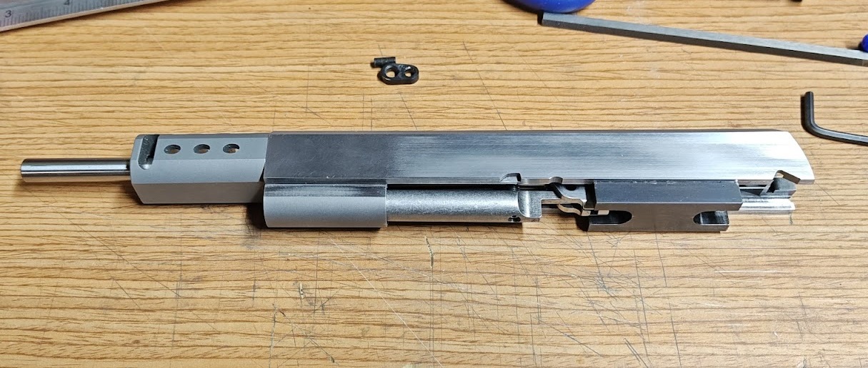 First, I place the barrel and the barrel holder mostly into the slide. Then the barrel alignment gauge is installed into the slide between the rails. The gauge has two open ends to accept the lower lugs, one being ever so slightly larger than the other. I use the tighter fitting of the two (or the only one of two which fits, depending on the barrel.) I push the barrel rearward until it engages with the barrel alignment gauge, then I insert the bore alignment gauge and press the barrel up and into battery until the bore alignment gauge fits into the firing pin hole. Once that's in place, I tighten the set screw on the barrel holder, then remove the barrel alignment gauge. Pictured is the slide and barrel with all three tools installed. After removing the barrel alignment gauge, I install the slide onto the frame, press it past battery, and then install the lower lug cutting tool. While pressing forward on the slide, I take small cuts into the lower lug until the thumb safety just clears the cutout in the slide and can click into place. The slide stop pin is a nominal .200" diameter. The lower lug cutter is .195" diameter. After cutting the lower lug, everything is removed and then the lower lug is fitted by hand. Until the lower lug was final fit it would actually "click" into full battery at the last 1/8th inch of travel. It was caused by that little nominal difference between the .200" slide stop and the .195" cutter. More updates coming soon. Was a bit distracted this week due to my kid's birthday party. |
|
|
|
[#29]
This is awesome! And a tag for future updates.
|
|
|
|
CA, USA
|
[Last Edit: leelaw]
[#30]
A little touch up, and fitting the other barrel.
 Both firing pin blocks are rounded at the bottom. After making a round, I cover the striking face of the hammer and the round of the firing pin block with blue Sharpie, cycle the slide, and look at the wear marks. I'm looking for a good contact across the face of the hammer, which corresponds to good wear across the radius of the firing pin block. 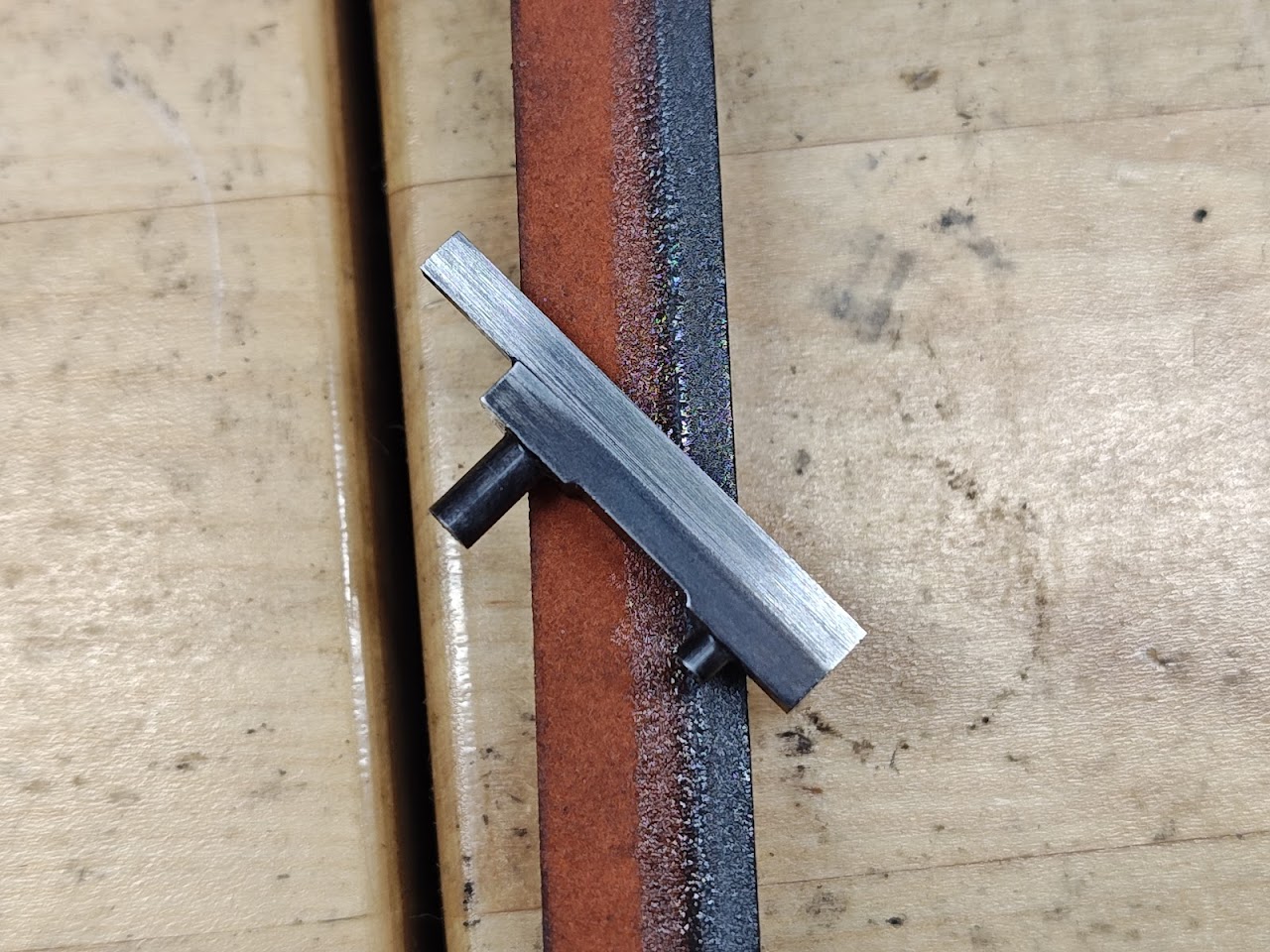 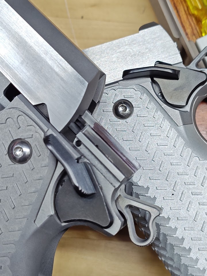 Originally I bought oversized ejectors for both pistols. That was probably a mistake. After fitting one, I decided to buy a regular long ejector from EGW. The fitment was easy enough - install the ejector, cycle the slide, see what rubbed where, then file off the points in contact. After filing away to a light friction fit, I use stoned to bring in the dimensions enough to have good clearance and a nice surface finish. Commander barrel fitting: 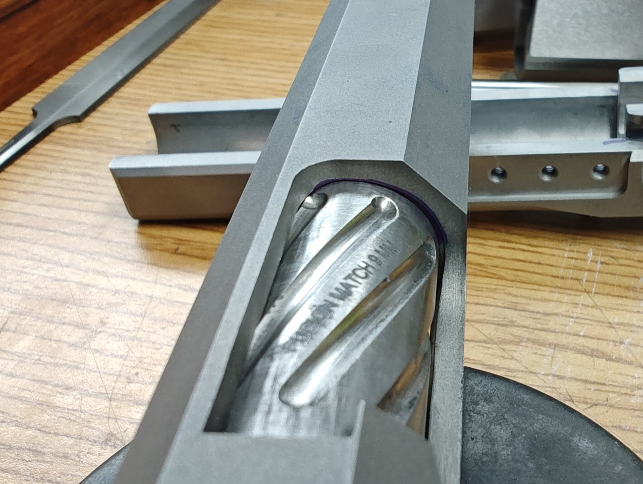 After fitting the hood to length and width, I test the amount of upper lug locking. 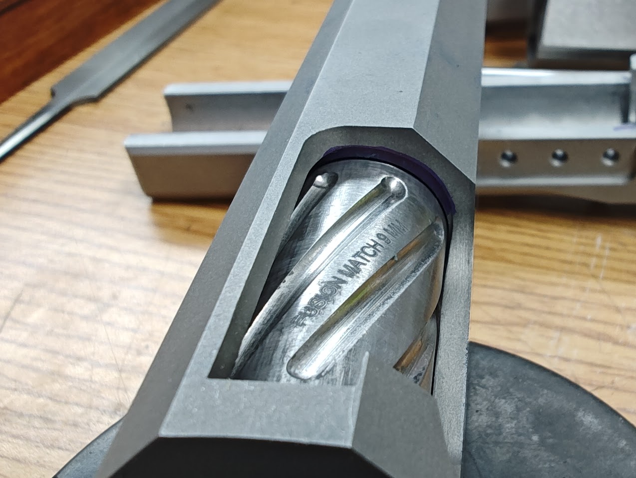 This is just a measurement of the lugs while the slide is installed on the frame and in the locked position, to just until the barrel clears the locking lugs and the slide unlocks. The goal is a minimum .045", and it's reading at .053" with a #4.5 link. So, let's see what's going on with the bottom side of the barrel: 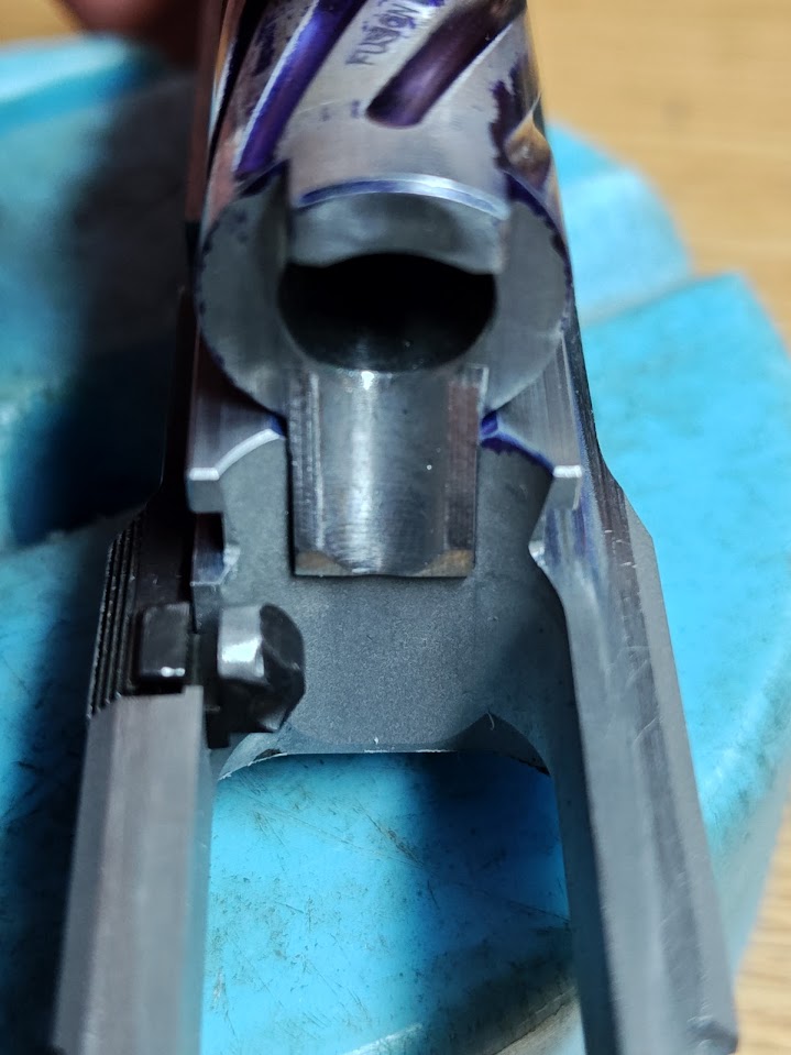 The ramp protrudes into the magazine well a little. Not ideal with a no-ramp barrel, but might be OK with a ramped barrel. Later, when I put the grip on for testing (of course I didn't take a picture of this - drat!), the magazine had plenty of clearance even when I pushed the barrel as far rearward as I could and I couldn't even force a conflict between the two. The top round, even if the nose dives, hits well on the ramp and doesn't get stuck at the bottom. This might be tinkered with during testing. 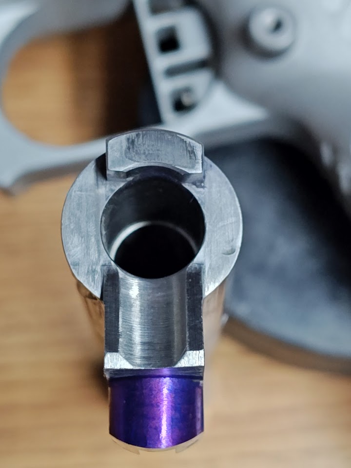 Well, there's supposed to be some kind of interference here with the Vertical Impact Surface. After some more testing, I found that the bottom of the ramp was too tall and prevented the vertical impact surface from touching the corresponding surface on the barrel. Carefully using files, I removed a couple thousandths from the bottom of the ramp and tested again. 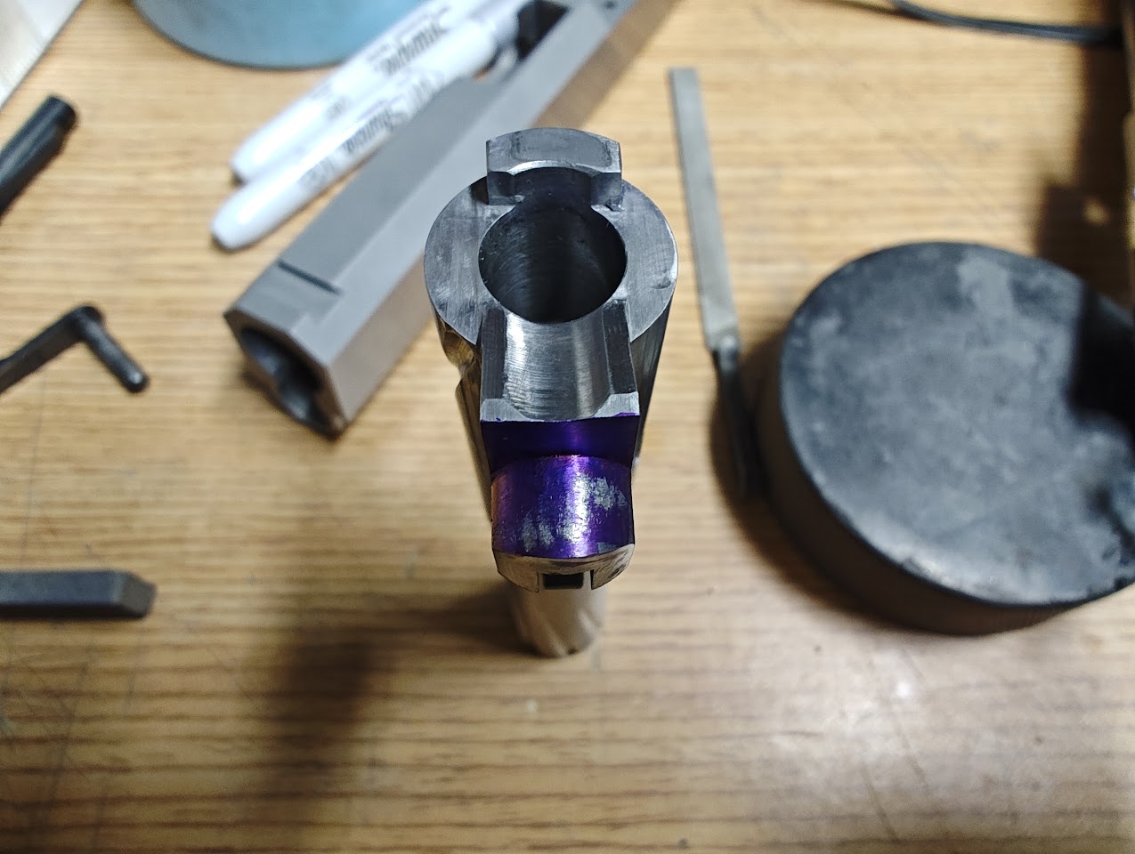 That's looking better. After using a thin strip of fine sandpaper, the contact patch looks even better. 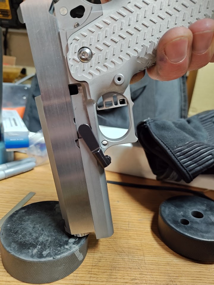 and testing confirms good contact with the VIS, a free swinging slide catch, and good clearance for the hood, with good amount of lock up on the upper lugs. This one ended up with a #4.5 barrel link. 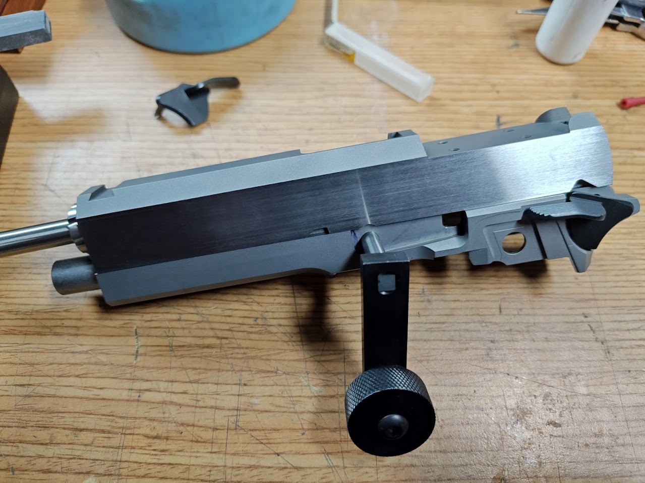 Then the lower lug is cut until the thumb safety just clicks into place, then gets filed and stoned to fit. After live firing, this might be adjusted slightly. |
|
|
CA, USA
|
[#31]
Lets fit some safeties.
This will be out of order. You should perform all final fitting with your hammer and sear BEFORE fitting the safety. If you're doing something like I am on this build (converting a traditional sear to a True Radius) then you will be removing some material from the nose of the sear. Depending on how much you remove, it might change how the sear will interact with the safety and might cause a dangerous condition. 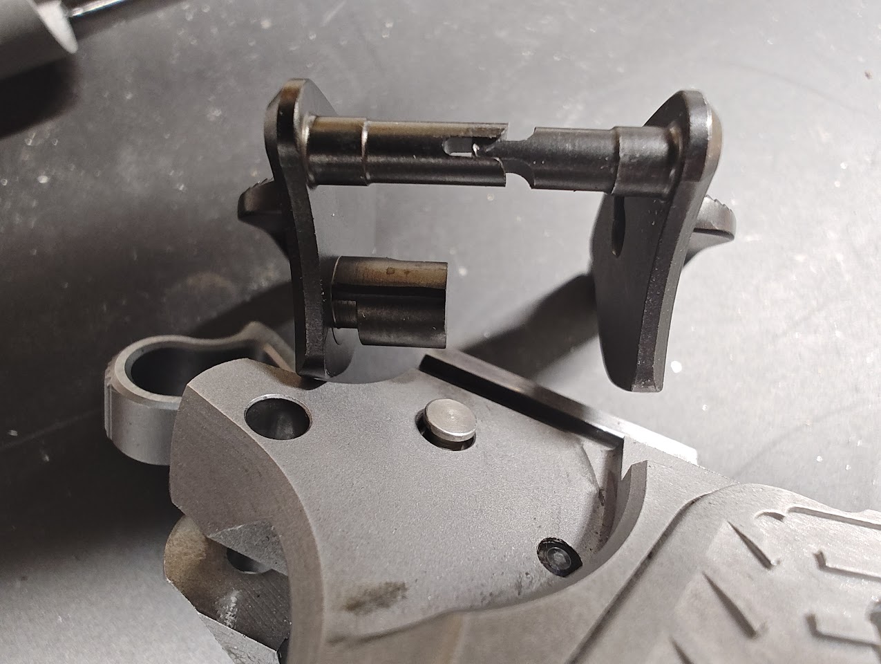 The safeties I'm using are EGW ambi-safeties, where the hammer pin also acts as a lock for the right side of the safety. The hammer pin is extended then cut so that it rides in a corresponding T-channel (or Keymod channel if you're really a fan) on the right side safety. The safety comes with foure different length hammer pins for various width of frames. In both of my cases, the longest pin fit for both. 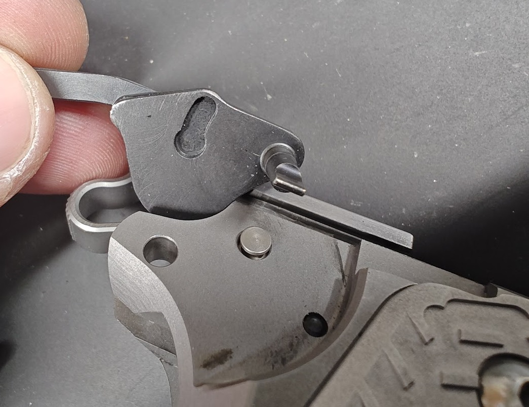 The first test is to remove all internals other than the hammer pin, install the right side safety, and check that it can move through the full range of motion without any snags or hangs. 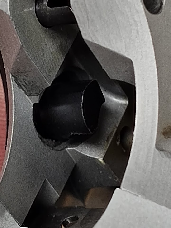 Then install the left side.... 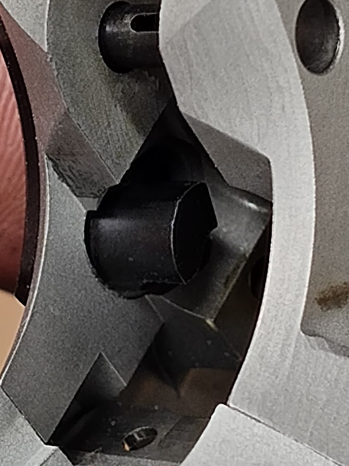 ...and test for full range of motion again. If the safety does not move fully into place, then use a thin file to relieve the safety. Don't cut into the frame to get the safety to fit. 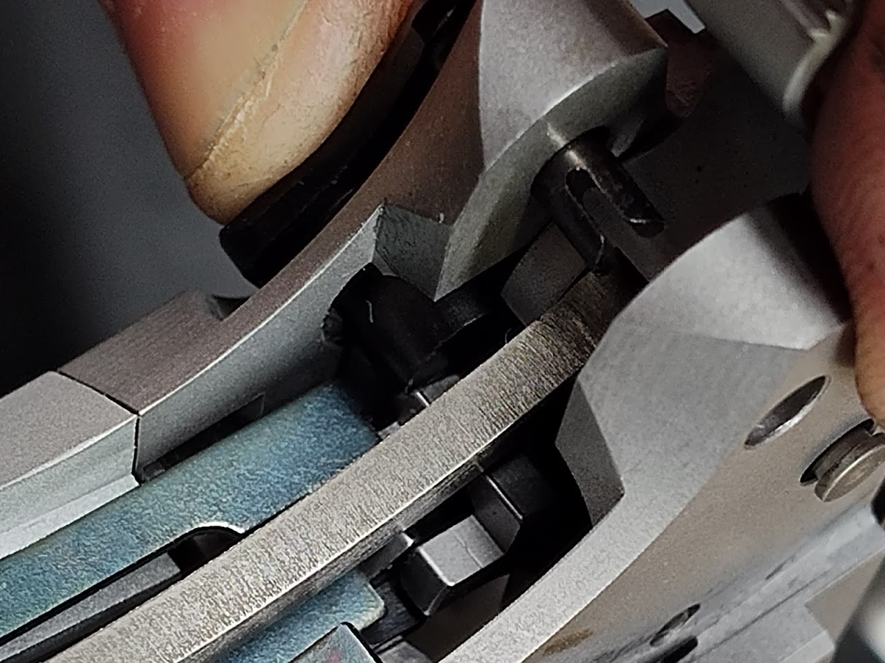 Then reinstall the internals and test fit the left side safety. It should strike against the sear. Look at where the sear is hitting the leg of your safety and start SLOWLY removing material to fit. After the safety fits in the neutral position (where it fits when you install it into the frame) then mark everything with blue Sharpie and try to push the safety up into Safe, and down into Fire. Remove a little bit from each location with wear marks, then rinse and repeat. I cannot stress enough that you take this step slowly. If you remove too much material, you will create an unsafe condition, and allow the hammer to drop while the safety is on, or allow the safety to drop to half cock when you release the safety. |
|
|
CA, USA
|
[Last Edit: leelaw]
[#32]
The prior mention of fitting an ejector has skipped some details. After hand-filing one gunsmith-fit ejector to fit, I wasn't convinced the juice was worth the squeeze. I'll get a post set just to compare the gunsmith fit to the minimally fit long ejector sometime later. I'm a bit behind on updates as my free time is getting chewed into. Ah, life....
Anyways, on to some sear and hammer sets. On both of these, I'm modifying both of the EGW sears to have a True Radius across the sear surface. The hammers are both C&S Super Match. 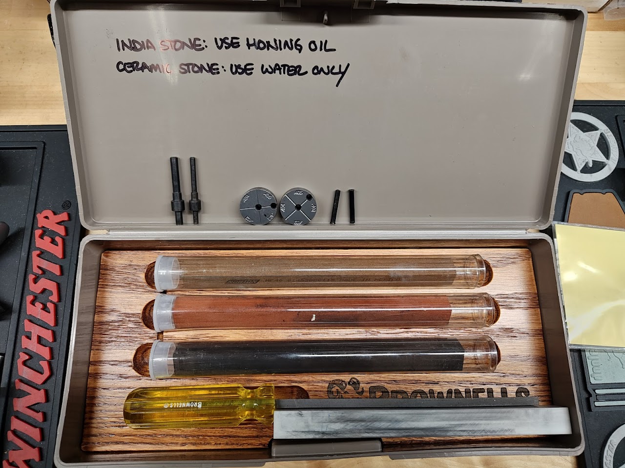 The basic tools I'll use for the sear work on these pistols. Stone and file kit, a sear and hammer offset pin set, and a True Radius kit from Harrison Custom. 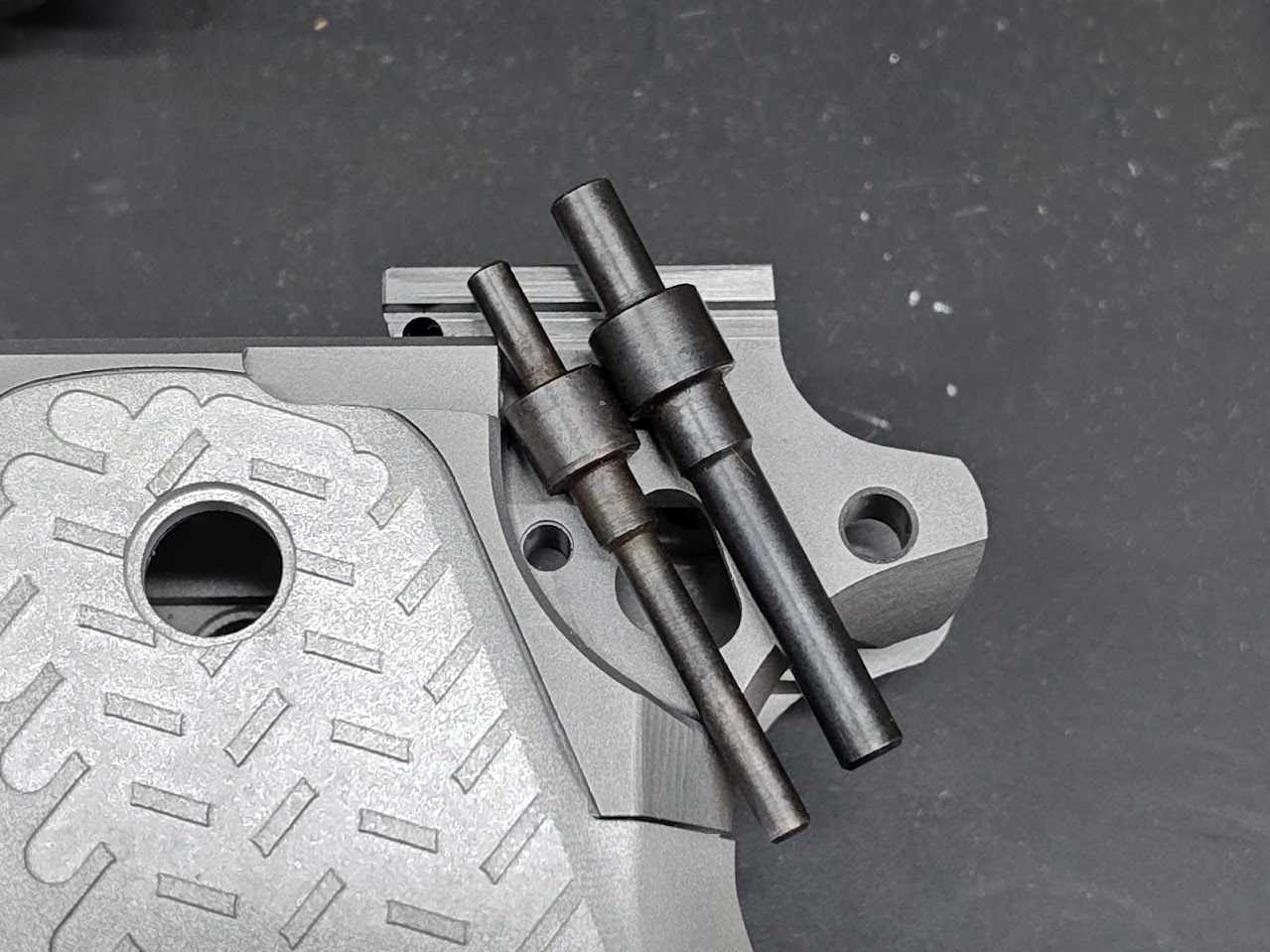 The offset pin set is helpful to observe the interaction between the sear and hammer while working on them, especially when setting the relief cut on the sear. 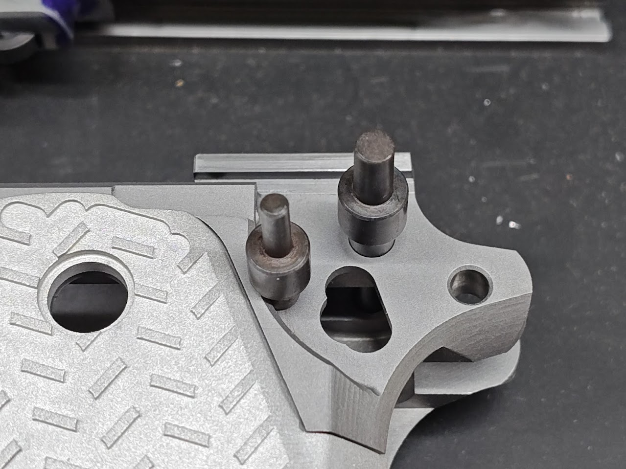 Pins installed. 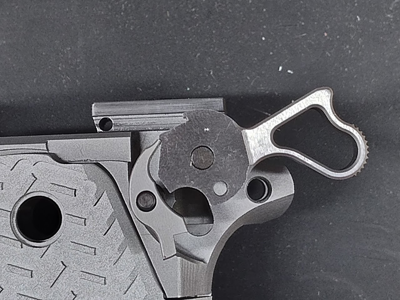 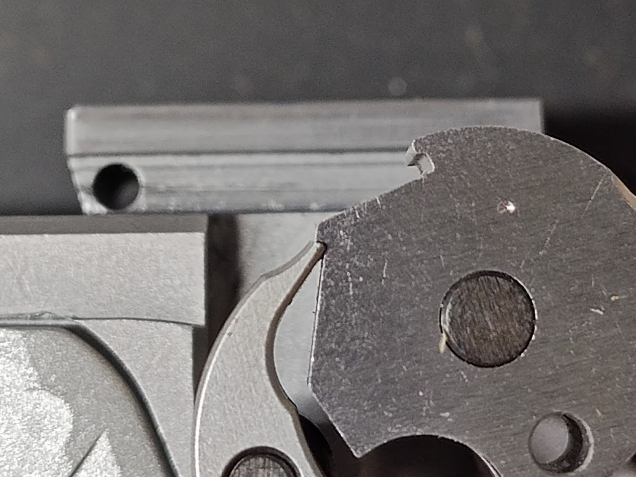 My cell phone is too technologically advanced to give decent macro pictures, I'm learning. This is the sear engagement before any work. 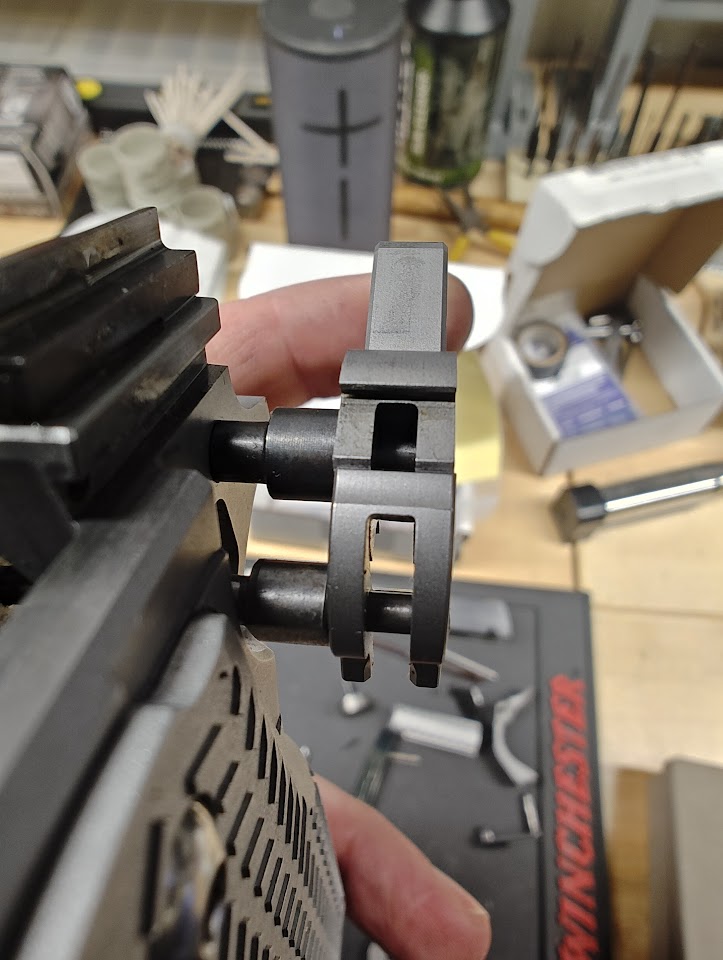 And observed from the front. 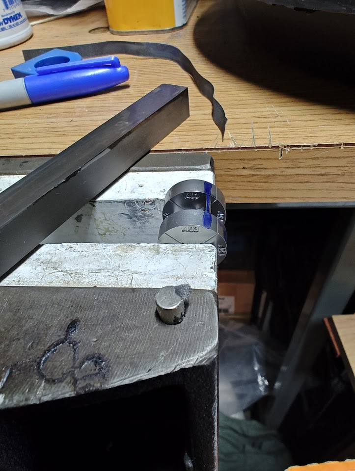 https://www.harrisoncustom.com/images/uploaded/pdf/HD-806%20True%20Radius%20PRO%20Sear%20Jig.pdf This instruction set from Harrison Custom about the True Radius set does a better job than I do at explaining things. I ended up using a few strokes of the fine india stone, then moved to the next smaller radius measurement and bringing it in with the extra fine india stone, then followed off with the ceramic. I'd show pictures, but all the ones I attempted looked pretty bad. 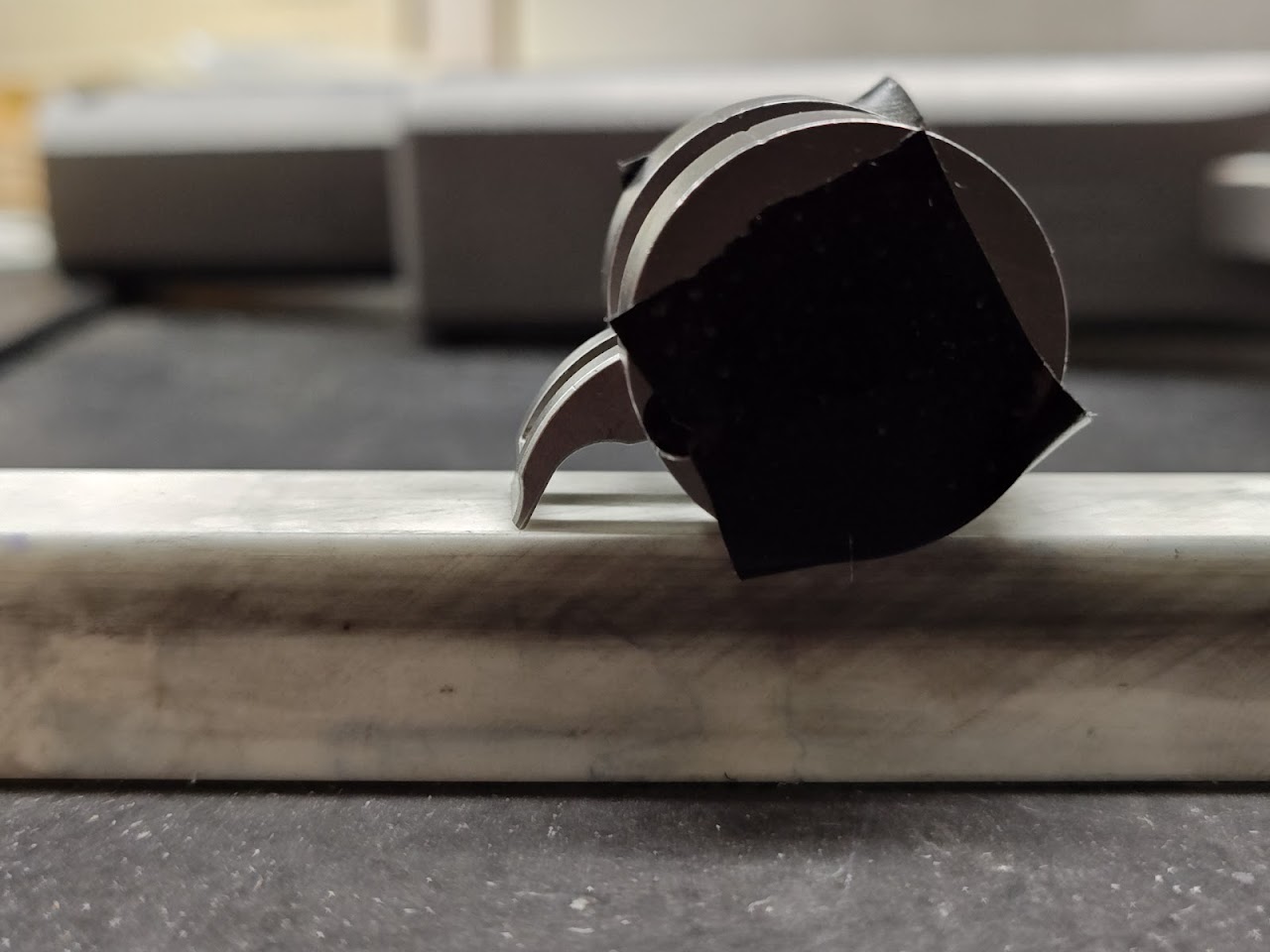 Using just the ceramic stone to set the relief angle, with electrical tape to give a slight offset to preserve the face of the jig. The relief cut is set pretty short, so there is room to take off more if desired. Without playing with the spring, this set both triggers right about 4 pounds. There is still a bit of room to wiggle in, and I'll get the government trigger under 2 pounds before all is said and done. I used the ceramic stone to true and polish the surface of the hammer sear. |
|
|
|
[#33]
The True Radius sear tool is one of the best tools ever.
|
|
|
|
CA, USA
|
[#34]
@supercomp
Finally took some weights today, just to give a good "before" picture. Government total (including optic mount, slide racker, and thumb rest, but not including the optic or magwell): 56.9oz Government slide (bare): 14.0oz Commander total (including optic mount, but not including optic or magwell): 36.5oz Commander slide (bare): 10.8oz For the recoil spring guide rod on the Commander, I'm using the Atlas commander tool-less guide rod. It's made only for the Atlas slides, which they advertise as being cut down Government slides (which makes for a shorter hood underneath the muzzle, more travel, so more dwell time during recoil, etc.) so it would not work with their recoil spring cap, but does work with a standard 1.25" cap from EGW. I'm not convinced that the Atlas solution is necessary, but it's something to consider if range testing shows a dwell time problem that can't be fixed with springs. |
|
|
|
[#35]
cool!
|
|
|
|
|
[#36]
Outstanding thread! Looking forward to seeing these come together.
You are a man of patience and your work looks incredible. |
|
|
|
CA, USA
|
[#37]
OK, after a little hiatus (work all last weekend, family trip the weekend before, sick the weekend prior) we're back to chipping off at this project.
I glossed over the ejectors. Originally, I bought full gunsmith-fit ejectors. They required every darn single dimension to be filed, sanded, and fitted into place. After doing one fully, I decided to buy a mostly--fit one on the Government. I'm undecided if the differences will be enough to get me to go back and do the Government one from scratch. It sure was a lot of work for minimal aesthetic difference. 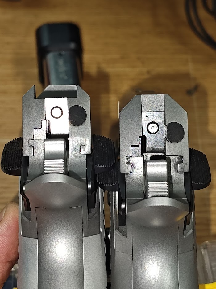 The Commander (gunsmith fit) on the left. The Government (mostly-fit) on the right. The large differences is with the Government with gaps at the tops of the ejector, and the radiuses and thinned area at the rear to make clearance for the hammer, being just short of a flush fit with the frame. On to the chambers. 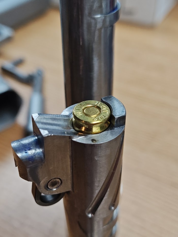 The Fusion Firearms barrel has basically a final finished chamber in it. It did not have any variances that makes me want to cut into it at all. The Bar-Sto barrel has a short chamber. 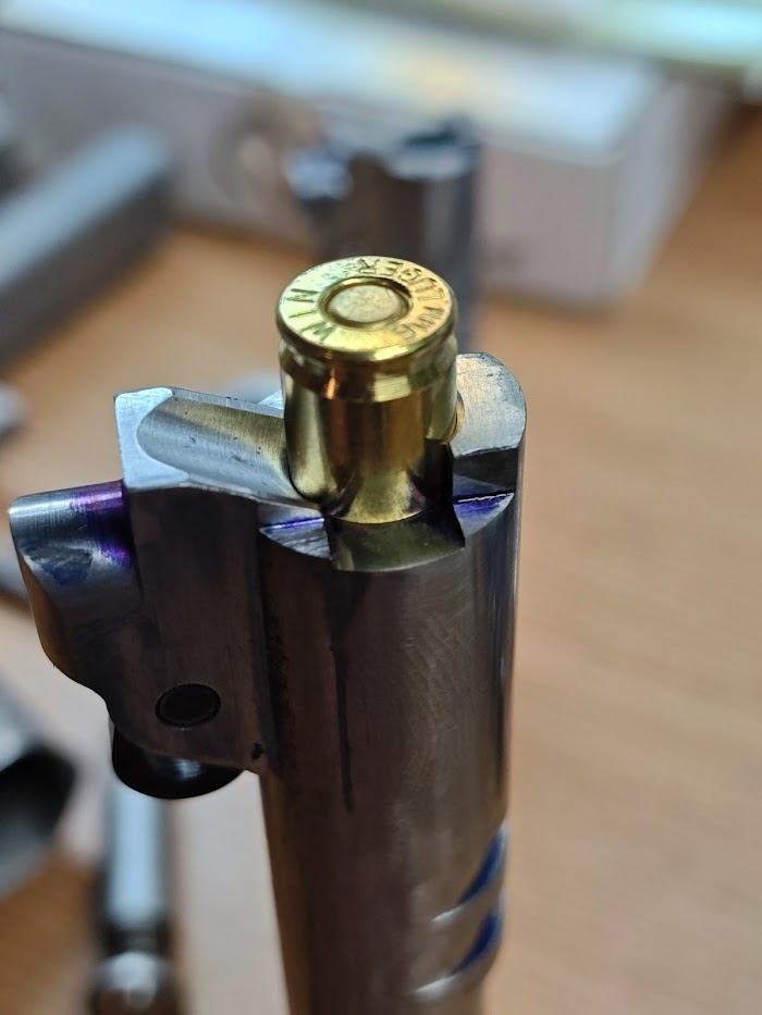 Like REALLY short. It needs to be cut down. I contacted Bar-Sto to get a quite for having them finish ream the chamber. It was about half the price of buying a beautiful Clymer finish chamber reamer with a bore guide. One option is to pay for a service. The other option is to pay twice as much, do the work yourself, and have a tool in the end. 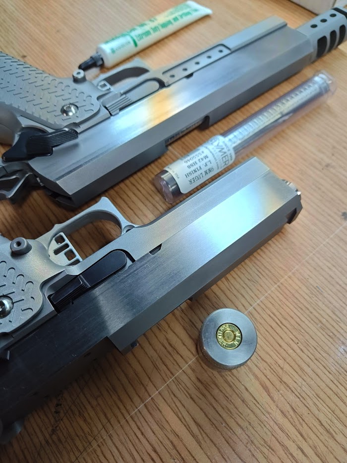 I'm a sucker for tools. 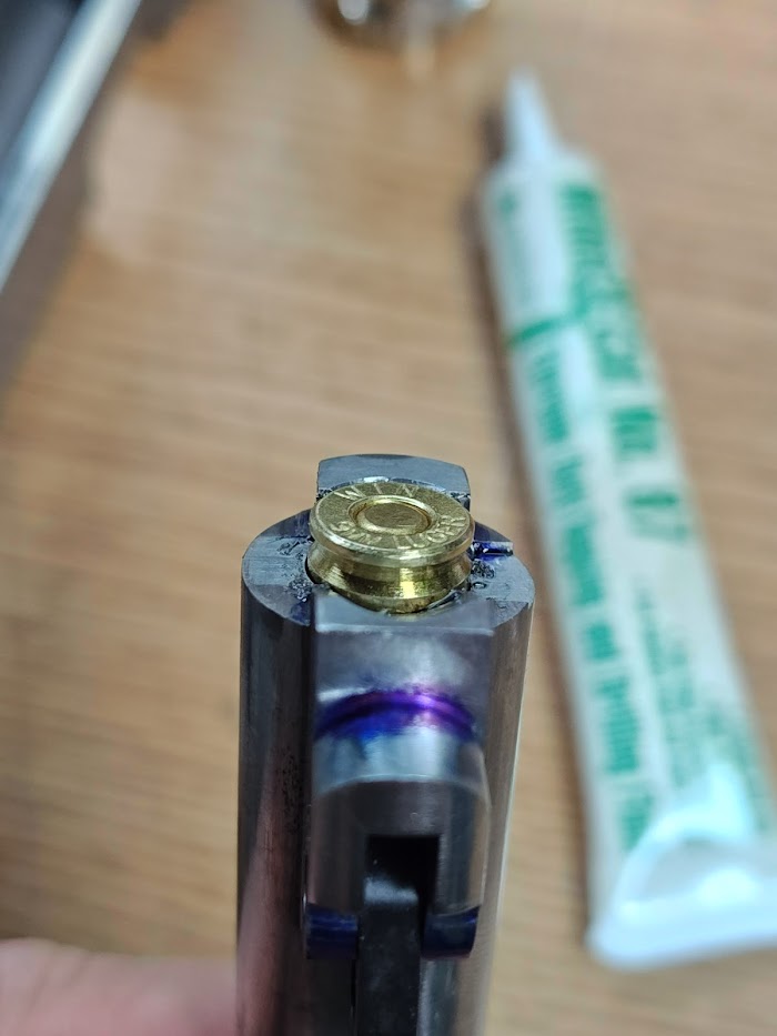 After about 45 minutes of very slow cutting, cleaning, removing chips, re-lubing the reamer, and repeating, the dummy I created fit perfectly (I realized today that I didn't have a true 9mm chamber gauge, so I used a case gauge to make a dummy to act as my GO-gauge. Hand cycling live rounds and testing with some shim stock shows this to be pretty accurate, but I'll let live fire testing later tell me the truth. Speaking of live-fire testing, we're basically ready to begin. I've cycled both pistols with dummies a couple hundred times. The extractors need to be tuned and the ejectors are too long, but to test the remainder of the system it's almost ready. Both of the ramps for the barrels extend into the magazine well a little like previously pictured. I've yet to have a failure to feed (though inadequate extractor tension will help allow that to happen) but I cannot get the magazines to impact with them, and the nose of the rounds hit well above the 50% mark, which means there's a bit of meat to play with if I need to change some angles later. I won't touch them until after some live firing. Thanks for keeping along with the thread. Hopefully have some more updates soon! |
|
|
CA, USA
|
[#38]
Had the opportunity to get to the range today, so I threw in the extractors with a rough rough springing. The claws of the extractor have had no work done to them (they'll eventually get some radii and polishing), the ejectors still have not been cut to length or tuned, the disconnectors are still tight, and other details.
There were many failures to eject and feed, as expected. The barrels feel properly tuned. There is no galling to suggest timing or lockup issues, but more testing will confirm that. No accuracy testing. I didn't bring out the ransom rest, and neither of them have sights installed. Glad to know they're somewhat functional. One small hurdle down! |
|
|
|
[#39]
Can you go into thumb safety fitting a bit more? All of the Atlas videos I have watched only mention using a #2 file and taking down enough material on the small leg of the "L" on the sear interface lug. Following Atlas' instructions, I was able to fit my thumb safety and pass all safety/function tests. You mention marking the lug and taking note of contact both in the safe and fire positions. Just curious to see if I am missing anything. I'm using an Atlas ambi carry thumb safety if that makes any difference.
|
|
|
|
|
[#40]
Awesome
|
|
|
|
CA, USA
|
[Last Edit: leelaw]
[#41]
Originally Posted By Advance: Can you go into thumb safety fitting a bit more? All of the Atlas videos I have watched only mention using a #2 file and taking down enough material on the small leg of the "L" on the sear interface lug. Following Atlas' instructions, I was able to fit my thumb safety and pass all safety/function tests. You mention marking the lug and taking note of contact both in the safe and fire positions. Just curious to see if I am missing anything. I'm using an Atlas ambi carry thumb safety if that makes any difference. @Advance That "L" area is where the majority of filing is done. I don't think the type of safety (paddle size, ambi, etc) matters since the ambi-side doesn't interface directly with the safety, and the lug on the safety should be pretty close to the same across manufacturers. After the hammer, sear and disconnector are fitted, then install the safety. Make sure the safety fits to the frame (no internals, see that it fits in then goes all the way up and down without snags. If it snags, relieve the gap between the flat of the safety that rides against the outside of the frame, and the lug that extends into the frame. Then fit the safety to the sear and hammer. Have the internals already installed, but keep the grip safety off so you can see what's going on. Push the safety into the frame until it bottoms out against the sear. Through the area where the grip safety would be, you can see where the sear is physically preventing the safety from entering the frame (on that "L" ledge.) You can use sharpie or dykem or some other layout fluid to see a physical impression where the safety hits. File away most of that portion of the safety, then slowly walk up to a final fit just to get the safety to fit into the frame. Now the safety will fit into the frame, but it's blocked by the sear from rotating up or down. I'll put sharpie on the filed edge, then push the safety up. If there is a wear mark, I file it a little, then repeat the process. Only remove material from where the sear is hitting the safety and rubbing off the sharpie. If you remove too much during this part of fitting, you deactivate your safety. This can be recovered from by peening out some material, but it's not ideal. Once I have full range of motion to the safe position, I repeat again going down into the safety-off position. Once the safety bottoms out, I test whether the safety actually gave clearance for the sear to move freely by pressing the trigger to drop the hammer (no springs installed.) If the sear hangs or doesn't allow the hammer to fall, I repeat the process with sharpie. Hope this makes sense. It makes sense to me, but I'm visualizing it while typing it out... |
|
|
CA, USA
|
[#42]
More testing.
After adjusting the tension down on the extractor and no other work (though there's still lots to do) the Gov went out to the range today for about 100 rounds. Absolutely flawless today, which was very pleasantly surprising. Hopefully some more work gets done this weekend. |
|
|
CA, USA
|
[#43]
Well, I broke down. The two different ejectors (one "gunsmith fit" and one "mostly fit/extended") are different enough aesthetically that I cut down and installed the second gunsmith fit ejector for the Government.
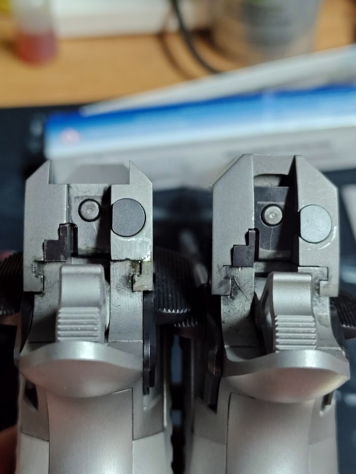 The fit is much better, but it's just aesthetics. 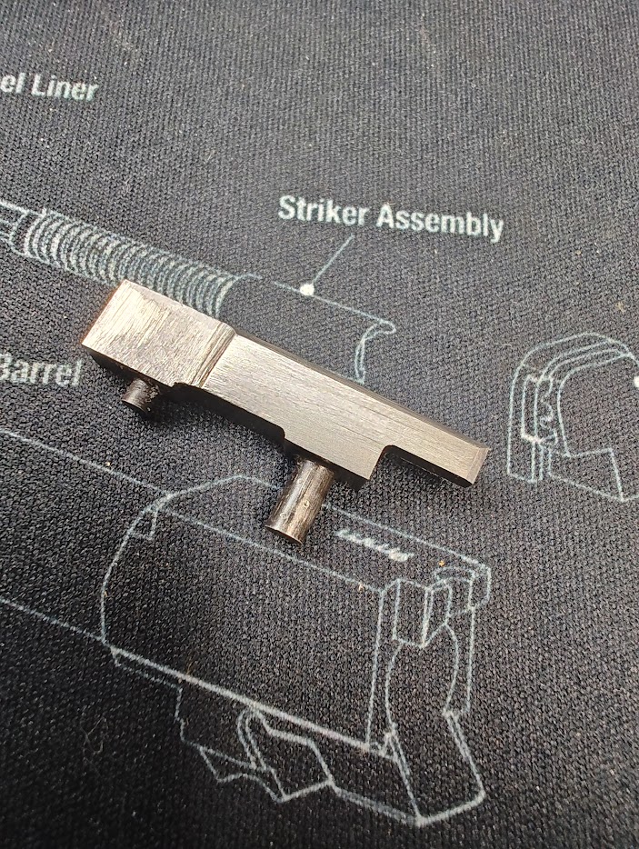 Then I cut down the ejectors to just over 1.1" overall (from where the rear of the ejector intersects the frame, to the nose) 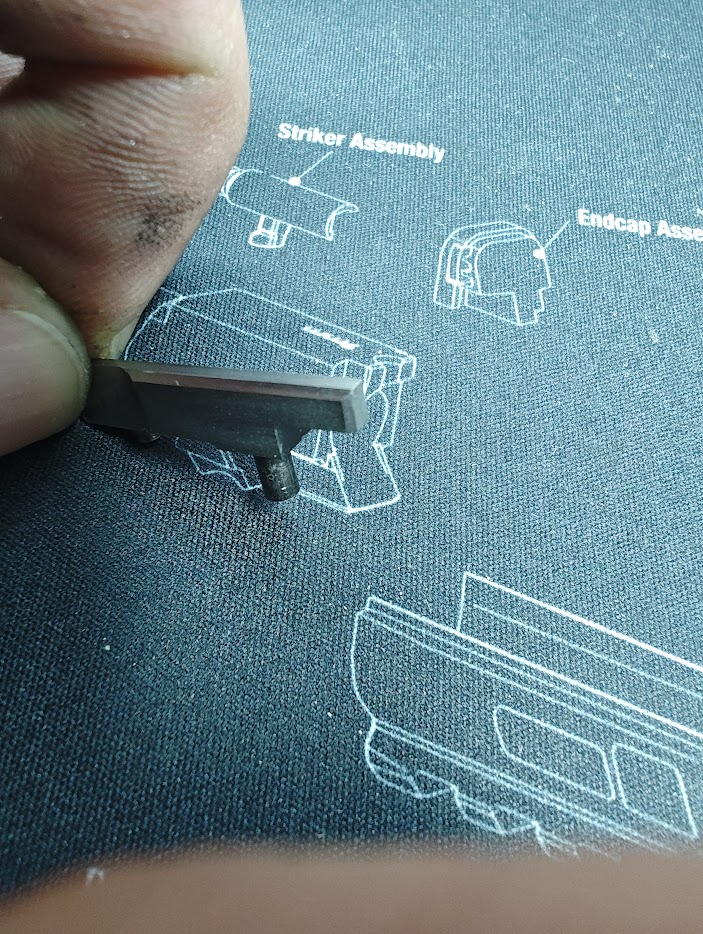 Then gave them some bevels and stoning. Hand cycling shows a better 3-4 o'clock ejection pattern compared to the 2-3 o'clock before. Live firing will give better direction. 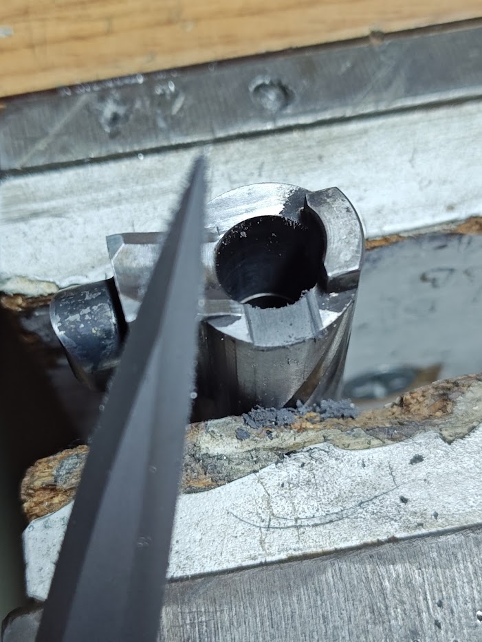 I had some issues with the Commander failing to go into battery without some assistance. Maybe 2-3% of the time. I found the nose of the extractor could rub against the rear of the barrel hood. Some hand filing in a relief cut made that interference go away. 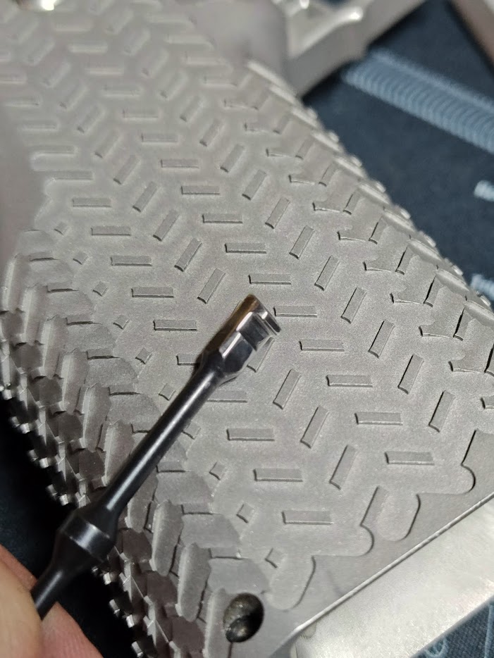 The bottom of the extractors got a slight radius. The claws were given a slightly positive rake angle, and the section of the extractor that rides against the rim of the ammo was given a polish. There is still some more work to do on all of these parts, in addition to the testing. Speaking of testing, these each have about 500 rounds through them and it's looking pretty darn good by now. Testing has also revealed some pinch points on the safeties that need to be contoured, the Commander slide stop needed an undercut so it could be activated a bit better, and some other small things I've found. The project is officially running late for the original July due date. |
|
|
CA, USA
|
[#44]
Dropped off at the machinist for some rendering, then milling of the slides and frames. No more updates for a while, I think.
|
|
|
 Win a FREE Membership!
Sign up for the ARFCOM weekly newsletter and be entered to win a free ARFCOM membership. One new winner* is announced every week!
You will receive an email every Friday morning featuring the latest chatter from the hottest topics, breaking news surrounding legislation, as well as exclusive deals only available to ARFCOM email subscribers.

AR15.COM is the world's largest firearm community and is a gathering place for firearm enthusiasts of all types.
From hunters and military members, to competition shooters and general firearm enthusiasts, we welcome anyone who values and respects the way of the firearm.

Subscribe to our monthly Newsletter to receive firearm news, product discounts from your favorite Industry Partners, and more.
Copyright © 1996-2024 AR15.COM LLC. All Rights Reserved.
Any use of this content without express written consent is prohibited.
AR15.Com reserves the right to overwrite or replace any affiliate, commercial, or monetizable links, posted by users, with our own.


