


Armory Sponsor

DIY Annealing Machine (Page 8 of 17)

|
Originally Posted By braindoc:
Thanks! I'm still not sure how to attach the motor to the frame and pan with only hand tools only . I don't have a lathe or a drill press, only a power drill. Is,it still possible to build a minimalist unit? If it helps, i built mine with basic handtools apart from the couplers. When i built mine, i built it from my head not from any real plans ( built it as it come ) all in all about 4hrs. I had other attemps prior to the final build that i posted up the final build and then later on made the plans for it up based off my build. Depending on your scavenging abilitys you can build it pretty cheap. The hand tools i used was drill, hammer, pencil, jigsaw, tapemeasure, screwdrivers, small nails, screws, nuts + bolts, liquid nails, paint, dremil and file. Mounting the motor, if you have stumbled accros my plans or others on there builds the motors i selected had mounts with the motor, so srews and bolts and nuts were only needed :) Your build can be as simple or as complex as you wish. There has been plenty of fantastic builds like some posted here and on other sites, others are also documenting there builds and keeping my wishes of the build to be free and open sorce. There are a number of vids now on youtube with people and there builds :) I dont think the OP has finished his build but a few here have, im sure the op will finish theres soon. Ive built a few for a few mates and have a couple more to build. I have another one in the memory bank that i will build and post in the future. But for now. Good luck with your build :) Skip |
|
Hello El-Skippo!
Glad you replied. I just signed up on your Aussie site tonight. I will be reviewing your pages to see the evolution of the annealers. I still plan to keep it very simple and compact so it will fit on my small reloading table top. Wish me luck. Regards, braindoc |
|
Originally Posted By spuddicus:
Does anyone have the dimensions on the main box that holds everything? I can eyeball one but why reinvent the wheel? Maybe this will help... 10”X12”X3” with a 14-18 degree tilt…ish. Case made of what ever you got... Ok stay away from plastic...but a clear case would be cool! Hmmmm El Skippo what you think? Anyway... 15 to 20 RPM DC motor PWM speed control the higher the Hz the better 4-6” rotor Rotor Hub 22-20 Ga wire. Power supply to match motor and PWM voltage Tempiliaq 750F / 399C Temperature Indicating Liquid P# 24423 Bernzomatic Pencil Flame Torch P# UL2317 Basic home hand tools. To date I have spent much $$$ in R&D. I have now cooked two durring testing. Way too much fun! You CAN do this! 
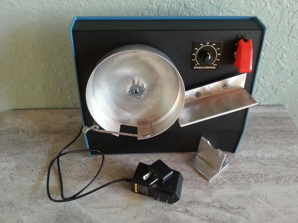
|

|
Originally Posted By ChevelleDave:
It's 1 3/4" Acetal, the slot will be determined by the case You intend to use. I went 1/4"x 1/4" for .223/ 300 Blackout. I stepped Mine down to 1 3/8ths to slide into the spacer plate. RLR covers this in one of His posts earlier in the thread. It's not immediately clear to me why the pick up drum has a shoulder stepped down, in your case, to 1 3/8". It seems to me that the inside edge of the drum should be close to the surface where the head of the case rests as long as it doesn't rub. that can be done with a straight cut pick up drum, no? Why the shoulder? |
|
The 'bare bones' model... While I really enjoy the work and craftsmanship that goes in so many of these on the thread, some truly stunning work....
This is for all the readers going, well crap no way I could do that... This was built with a jig saw and a hand drill, a countersink bit, a 5/8" spade bit, a soldering iron and solder and some heat shrink tube, a hacksaw. The original wood that I used this scrap piece from was cut with a power saw so there are some burn marks on a couple of edges but I think they add character. THe wood was a scrap piece of 12" wide by about 48" long oak plywood from a furniture project for the kids. Other than the motor, controller (from the first apge of the thread) all I bought was an L bracket to act as the ramp and the cake pan so I'm out $25-$30 in materials? Give or take. I chopped the board into sections, split a 13" section into two on a bias with a 5" and 8" end to each to make the slanty sides, another one in two pieces to make the top and the back and then screwed it all together with sheetrock screws. The back is open for about 5" at the bottom for ventilation and there's a gap in the front at the bottom of about 1/2" to give air flow. An old PC power supply that I clipped all the wires except yellow and black and then soldered those all together. the green and black wires from the main cable harness were soldered together to make the power supply come on. The cake pan was cut by the simple method of putting a pencil on a piece of wood trimmed to the height I wanted and then spun the pan in a circle with the pencil against the side to make a level line. A hack saw, slow but surely, cut the pan down without (much) flexing. After it was cut down I pressed the pan against a piece of wood with a speed square on it and drew a hole lot of lines on a 45. This left a O in the center of the pan, kind of like that old game with the gears and pens, spirograph? I used a drill bit to drill through that and it's (mostly) centered. There's a slight back and forth of about a 32nd of an inch. Good enough for gubbmint work. If I was smart I'd of cut the hole first before going through all that effort to hacksaw the thing in half just in case it was really wobbly but it worked out. A jig saw cut out the hole in the front plate for the motor and the included brackets are just screwed down from the front. Could have used a hole saw but this was 'what's the fewest tools you can get by with' attempt. Oh I had to buy a collar from the local hardware store, that was a buck or so. My bubba way to mount the pan was to put the pan on the shaft, then put on a piece of double sided tape with a hole in it down over the shaft and onto the pan and then press the collar down and tighten the screw onto the flat. Stupid? Well yeah. Does it work and cost me nothing? Well yeah. I used the 5/8" spade bit to drill out the holes for the power switch and rheostat. The jigsaw took care of the hole for the display panel. The $1.29 L bracket from Lowes over in the construction section of the lumber area where they have all the 2x4 type connectors I chopped a corner off with the hacksaw so it would but up against the pan. The retaining rod is a piece of rod stock I had laying around that I just bent with a pair of vice grips to the shape I wanted. It's actually just duct taped to the side at the moment as I was tring to see the best spot for it. Now that I have it I'll attach it more permanently with a piece of wood or piece of thin steel plate or whatever I can dig up in the scrap bins. Took me a minute or two to realize the back of the ramp has to be out a fair bit from the back of the pan or the cases nose dive and go sideways. Every case dropped in and swung sideways. WTH? Everyone else's works?! Then I took a closer look and aha, I moved the ramp out on another piece of wood and that fixed that and it handles 308 and 556 fine. The 556 is too short to work with the pan as is but I'll cut out a piece of 1/4" ply in a circle and drop in the pan to fix that when I want to do 556 and just move the retaining rod out a 1/4" or so. The propane torch will just sit on holder I have yet to make. Just some pieces of wood with U shapes to hold things in place. So about an hour's worth of work, a jackson and a half out of my pocket and I have a case annealer. It is a hand feed but that's fine with me. What I mostly wanted it for was precision reloads and I don't go through a 100-200 a month of those. Anyway, anyone thinking they can't make one of these that may be ugly as sin but fully functional, this should prove anyone can do it. 
|

|
Originally Posted By Mozella:
It's not immediately clear to me why the pick up drum has a shoulder stepped down, in your case, to 1 3/8". It seems to me that the inside edge of the drum should be close to the surface where the head of the case rests as long as it doesn't rub. that can be done with a straight cut pick up drum, no? Why the shoulder? Originally Posted By Mozella:
Originally Posted By ChevelleDave:
It's 1 3/4" Acetal, the slot will be determined by the case You intend to use. I went 1/4"x 1/4" for .223/ 300 Blackout. I stepped Mine down to 1 3/8ths to slide into the spacer plate. RLR covers this in one of His posts earlier in the thread. It's not immediately clear to me why the pick up drum has a shoulder stepped down, in your case, to 1 3/8". It seems to me that the inside edge of the drum should be close to the surface where the head of the case rests as long as it doesn't rub. that can be done with a straight cut pick up drum, no? Why the shoulder? You might be able to do it without the step down. However, with the step down the wood wall keeps the case from sliding back. If it slides back into the groove it won't fall out and will clog the drum. The step down is an easy way to ensure this doesn't happen. Without the step down if the case does move backwards it could be prevented with a set screw acting as a stop. Since I used the step down to prevent this, I really have no idea if it was really needed. |
|
Here is the video of mine working. Been following this thread and I'm really glad I found it. I had a great time building this thing. I think I took some piece of advise from each of you who posted info, so thank you for sharing. My friends are pretty impressed with this thing, and I think I'm going to be annealing everyone's brass now. :(
https://youtu.be/kCH7OJI5Wlc Here are also some pics of the finished annealer. Painted red/black with the controls mounted on top. |

Global Warming Hoax Skeptic before it was cool
Joined:
Jun 2007
Posts:
35173
EE: 100% (1)
 WA, USA
|
Originally Posted By todd57: Here is the video of mine working. Been following this thread and I'm really glad I found it. I had a great time building this thing. I think I took some piece of advise from each of you who posted info, so thank you for sharing. My friends are pretty impressed with this thing, and I think I'm going to be annealing everyone's brass now. :( https://youtu.be/kCH7OJI5Wlc Here are also some pics of the finished annealer. Painted red/black with the controls mounted on top. https://drive.google.com/file/d/0B2KTpQk5NVntZHZVS2pLR0d4WFU/view?usp=sharing https://drive.google.com/file/d/0B2KTpQk5NVntNGV5TnFfN21yQTA/view?usp=sharing But now that I quoted your post, folks can click on the links above to see your pics. You are allowed to post pics, go up to FAQ's (top of the page) to learn how. |
Selling agent for Algores carbon credit scam.
Shooting and Reloading, one hobby feeds the other.
Shooting and Reloading, one hobby feeds the other.

|
Originally Posted By dryflash3: You have to be a Team Member to embed vidoes. But now that I quoted your post, folks can click on the links above to see your pics. You are allowed to post pics, go up to FAQ's (top of the page) to learn how. Hey Dryflash, I accidentally clicked the "block" button on his post. I don't know who the notification goes to so I am letting you know. |
O Lord, bless this thy hand grenade that with it thou mayest blow thine enemies to tiny bits, in thy mercy.
Global Warming Hoax Skeptic before it was cool
Joined:
Jun 2007
Posts:
35177
EE: 100% (1)
WA, USA
|
Originally Posted By MonkTx: Hey Dryflash, I accidentally clicked the "block" button on his post. I don't know who the notification goes to so I am letting you know. Originally Posted By MonkTx: Originally Posted By dryflash3: You are allowed to post pics, go up to FAQ's (top of the page) to learn how. Hey Dryflash, I accidentally clicked the "block" button on his post. I don't know who the notification goes to so I am letting you know. If I do hear about it, I will explain the mistake.  |
Selling agent for Algores carbon credit scam.
Shooting and Reloading, one hobby feeds the other.
Shooting and Reloading, one hobby feeds the other.
|
This will have to be in several parts because I have a 2000 character limit.
Thanks to all the wonderful posts in this thread, I was inspired to built a DIY Case Annealer. The basic design is an almost exact copy of Skip's final version with a few refinements and enhancements of my own. I sourced the components from places mentioned previously in this thread. What follows is how my machine differs from the ones already posted here. I understand the burning desire to use up that old sheet of 3/4" plywood lying around the shop, but I didn't need an emergency jack stand for my M1A2 Abrams Main Battle Tank. Consequently I elected to use thin plywood for the enclosure. I bought a quarter sheet (2'x4') sheet of .200" plywood from Home Depot. I don't know what species it is, but it has a fine cabinet grade face ply and the back face is nearly as good. Of course, .200" plywood is too thin to edge-fasten, so I glued in 3/8" square stock along all the joining edges. This takes a little time but hardly any additional cost. It certainly makes a more elegant box which is in keeping with the size and scale of the project. I got rid of all my large power tools when I moved to Italy, so I don't have a table saw to cut the panels. I laid out the design and then cut the pieces slightly oversized using a jitter saw. Then I clamped the 3/8" sticks along the layout lines and after the glue cured, I trimmed the edges using a 6" Stanley Low Angle Block Plane. If you're a wood worker and don't have one of these tools, do yourself a favor and buy one. Accept no substitutes. 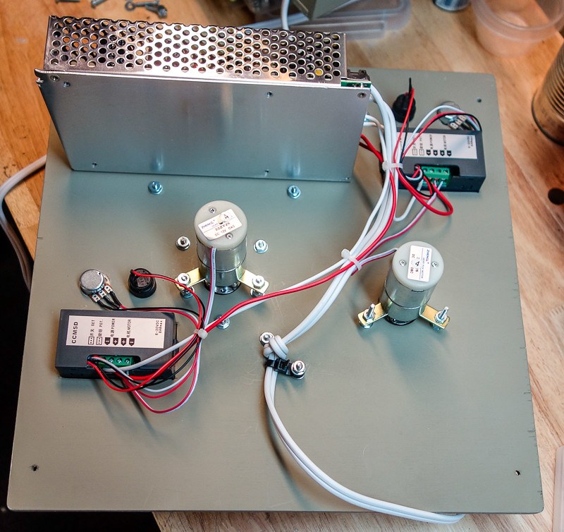
|
|
Part Two:
I fabricated a 5 sided box to which I attached a removable face plate fastened at the corners with 6-32 T-nuts. I added an additional piece of 3/8" square stock at each corner to accommodate the T-nuts. You could use wood screws to fasten the front face but T-nuts seemed nicer. I cut an oval shaped access port on the lower part of the back of the box so that I could stuff the power cord inside the box when not in use. I also used a 1" hole saw to cut a series of holes near the top of the back surface for cooling. Every component is attached to the face plate. Nothing is fastened to the other 5 sides of the enclosure. That design feature simplifies the wiring and makes it real easy to adjust and fiddle with the various components and pieces of hardware because the face plate and all the components, including the power cord, are entirely separate from the rest of the enclosure. However, this forced me to make the box slightly larger than some. Mine is 13" x 13" on the face. Still, you have to use some care when you lay out the location of the components so that they don't clash with one another. Nearly all the fasteners are 6-32. You'll need a 6-32 tap and appropriate drill bit. You'll also need a 1/2" and 1" Forstner bit and a set of hole saws. The case hopper and feed ramp are made from 2"x2"x.063" aluminum. No need to use 1/8". It's just harder to work with. I trimmed one edge to about 1/2" with a metal blade on my jitter saw in order to make mounting easier. |
|
Part Three:
I decided to spend a few extra bucks to purchase Acto Botics brand hubs from Servo City (Servocity.com). After all, why buy a 300 dollar case annealer when you can build one for 400 bucks, right? I used two 8mm set-screw-style (Acto Botics also make pinch-style hubs) and two matching spacers for the pie-pan drum and feed drum. The one inch OD spacer fits about half way into a recess I counter bored on the end of my Acetyl feed drum and the matching boss of the hub centers up nicely on the spacer. I drilled through the threaded mounting holes of the hub and fastened the hub and spacer to the Acetyl plastic feed drum with long 6-32 machine screws. It makes a neat and accurate way to mount the drum to the motor shaft. I used a 1/2" Forstner bit in my little table top drill press to bore a slot in the feed drum for the cases. I quit drilling 1/16" from the end to form a stop for the base end of the cases. It's important to align the base of this stop with the front face of the plywood spacer plate. This built-in stop and the used of the Acto Botics hub eliminates the need to use a lathe to reduce one end of the feed drum. The hub and spacer assembly fits into a recess formed by the spacer doubler and the box face plate. You can see this in the out-of-focus photo (sorry). By the way, the spacer plate is also made from .200" plywood. That works just fine, but you have to be reasonably accurate with your building and adjusting.  _DSC3261 by Mozella55, on Flickr _DSC3261 by Mozella55, on Flickr
|
|
Part Four:
I used the other hub and spacer to sandwich each side of the pie-pan with the hub on the outside so the pan can be easily removed or adjusted in-and-out as required. I followed the advice of other builders to make sure the cut-out in the pan goes all the way to what was once the bottom surface of the pie-pan and to adjust the pan in-and-out so as to align this surface with the face of the plywood spacer piece. It seems to work and the cases fall into the pan and orientate themselves reliably every time. If you trim the length of the little locking ears on the back of the two display boxes, they will snap into a carefully cut square hole in the face plate without the need for a thin auxiliary mounting plate. But you'll have to counter bore the back of the face plate to accommodate the speed trimming pots because they have very short shafts. I used a little end mill cutter in my Dremel tool. I took a look at the various ways other people have built and fastened the rod on which the cases ride while in the annealing pan. It seemed that the typical rod design gathered an unnecessary amount of heat from the torch because it's mounted just behind the case and therefore is directly in the flame. I used a piece of 1/4" steel rod and bent it into a contorted shape so that it is mostly inside the pan and out of the way of the flame. A look at the photo makes the idea clear. 
|
|
Part Five
A little sanding and a quick spray with some ultra-flat camo paint finished the job. Initial testing proved promising but occasionally the cases failed to feed. I realized that the mouth of the feed trough was EXACTLY four cases wide. From time-to-time, four cases would perfectly align along the bottom row and none of them would to drop into the feed drum slot because they would jam on the tapered sides of the aluminum feed trough. The simple solution was to remove one side of the feed trough and bend the lower end inward slightly so that the mouth of the trough where it meets the feed drum is a little bit less than four cases wide. Now it feeds without hesitation. 
Thanks again to those who have gone before me and refined this elegant design to where it is now. I'm sure others who follow will make further improvements and tweaks. By working together, we who reload ammunition and also have a strong obsession to build stuff can continue to make the shooting sports even more expensive and time consuming than it already is. |
i havent been around arfcom lately. School and family have consumed my time. So i have been doing research at work on round belting for a project have decided since i havent done much with my annealer i want to do a single motor design. since I have 6 weeks off before summer classes i am going try and get things drawn up. the biggest thing i need to try and make a commercial available parts list to keep things simple for ppl without maching capability. glad this tread is still going and ive seen it spread to other forums. sorry i ran out of steam on helping answer questions life got me.
|
|
Mozella, great build mate :)
You have got the right idea for the case stopper, that will reduce the heat dramaticly ( ive been passing on a similar way for awhile now via pms from all over the place. But you have hit the nail on the head. So much so its even better then the alternitive means i had been suggesting. So much so i wish to rid mine off V2 and incorperate that case stopper into my V2 build thats been going slowly the last month. Im part way through a V2 Its a single larger motor using cnc/3d printing parts to run the case feeder. ( t5 pulleys and a t5x10 type belt ) just waiting on a couple of new parts from china as i stuffed up ( i needed two sizes not just the one size bore for the pulleys ) Its much more involved in cost, then just the motor and Speed controller( the cost of the two pulleys alone is the same cost of the motor and controller, the extra cost comes in the shaft, 2x self center bearings, the t5x10mm belt plus the bits pf steel from the home hardware, its almost 3x the cost then the motor+ controler combined. All parts are sorced from ebay, to keep it simple for everyone and all built with basic tools etc nothing fancy needed and a few bits from your local hardwear will get you a V2 :) will be larger ( mine will be as i am doing every man and his dogs brass ) Black betty is still kicking ass, the amount of brass i have annealed with it i half expected it to give up the ghost. But she is still going like a champ :) No snecky pics yet, just have to wait till she is done. ( its twin sister two ) for a custom bullet maker freind of mine im building the twin for. Regards Skip |
Global Warming Hoax Skeptic before it was cool
Joined:
Jun 2007
Posts:
35232
EE: 100% (1)
WA, USA
|
Originally Posted By Mozella: Part Five A little sanding and a quick spray with some ultra-flat camo paint finished the job. Initial testing proved promising but occasional the cases failed to feed. I realized that the mouth of the feed trough was EXACTLY four cases wide. From time-to-time, four cases would perfectly align along the bottom row and none of them would to drop into the feed drum slot because they would jam on the tapered sides of the aluminum feed trough. The simple solution was to remove one side of the feed trough and bend one end inward slightly so that the mouth of the trough where it meets the feed drum is a little bit less than four cases wide. Now it feeds without hesitation. http://<a href=https://farm8.staticflickr.com/7758/17419202935_6062cab670_b.jpg Thanks again to those who have gone before me and refined this elegant design to where it is now. I'm sure others who follow will make further improvements and tweaks. By working together, we who reload ammunition and also have a strong obsession to build stuff can continue to make the shooting sports even more expensive and time consuming than it already is. Nice build and a good series of posts. Well done. |
Selling agent for Algores carbon credit scam.
Shooting and Reloading, one hobby feeds the other.
Shooting and Reloading, one hobby feeds the other.
|
Has anyone tried to use a cut-down #10 food can as the main rotor? I've looked through this thread a few times and don't recall seeing it. Tophatman suggested it in an IM exchange, and I just so happened to have one sitting around. The cans are just a shade over 6" in diameter and are straight up from the base (no draft angle like the aluminum cake pans); the size and shape appear to be perfiect. There's some type of coating on the inside, but I expect it will burn off in rather short order (outside, probably in a fire pit...).
I've ordered a motor through Amazon since I couldn't stand the wait. It's a little different than the one listed in the opening post, but ought to work just as well once I figure out a coupling and bearing setup. My PWM choice appears to be identical to the one shown here, and was also ordered from a stateside vendor due to the speed of delivery. I have two more on order from the folks in China just in case I can't make my idea for a mechanical feed work 
All other hardware excepting the torch extension hose will be sourced from found scrap or components I have at home. The good news is that I have a great deal of said scrap and components to choose from at work, plus I have AutoCAD and a CNC router to help make this work :) |

|
Originally Posted By corruptor: Has anyone tried to use a cut-down #10 food can as the main rotor? I've looked through this thread a few times and don't recall seeing it. Tophatman suggested it in an IM exchange, and I just so happened to have one sitting around. The cans are just a shade over 6" in diameter and are straight up from the base (no draft angle like the aluminum cake pans); the size and shape appear to be perfiect. There's some type of coating on the inside, but I expect it will burn off in rather short order (outside, probably in a fire pit...). I've ordered a motor through Amazon since I couldn't stand the wait. It's a little different than the one listed in the opening post, but ought to work just as well once I figure out a coupling and bearing setup. My PWM choice appears to be identical to the one shown here, and was also ordered from a stateside vendor due to the speed of delivery. I have two more on order from the folks in China just in case I can't make my idea for a mechanical feed work All other hardware excepting the torch extension hose will be sourced from found scrap or components I have at home. The good news is that I have a great deal of said scrap and components to choose from at work, plus I have AutoCAD and a CNC router to help make this work :) |
|
Originally Posted By El-Skippo:
If it helps, i built mine with basic handtools apart from the couplers. When i built mine, i built it from my head not from any real plans ( built it as it come ) all in all about 4hrs. I had other attemps prior to the final build that i posted up the final build and then later on made the plans for it up based off my build. Depending on your scavenging abilitys you can build it pretty cheap. The hand tools i used was drill, hammer, pencil, jigsaw, tapemeasure, screwdrivers, small nails, screws, nuts + bolts, liquid nails, paint, dremil and file. Mounting the motor, if you have stumbled accros my plans or others on there builds the motors i selected had mounts with the motor, so srews and bolts and nuts were only needed :) Your build can be as simple or as complex as you wish. There has been plenty of fantastic builds like some posted here and on other sites, others are also documenting there builds and keeping my wishes of the build to be free and open sorce. There are a number of vids now on youtube with people and there builds :) I dont think the OP has finished his build but a few here have, im sure the op will finish theres soon. Ive built a few for a few mates and have a couple more to build. I have another one in the memory bank that i will build and post in the future. But for now. Good luck with your build :) Skip Originally Posted By El-Skippo:
Originally Posted By braindoc:
Thanks! I'm still not sure how to attach the motor to the frame and pan with only hand tools only . I don't have a lathe or a drill press, only a power drill. Is,it still possible to build a minimalist unit? If it helps, i built mine with basic handtools apart from the couplers. When i built mine, i built it from my head not from any real plans ( built it as it come ) all in all about 4hrs. I had other attemps prior to the final build that i posted up the final build and then later on made the plans for it up based off my build. Depending on your scavenging abilitys you can build it pretty cheap. The hand tools i used was drill, hammer, pencil, jigsaw, tapemeasure, screwdrivers, small nails, screws, nuts + bolts, liquid nails, paint, dremil and file. Mounting the motor, if you have stumbled accros my plans or others on there builds the motors i selected had mounts with the motor, so srews and bolts and nuts were only needed :) Your build can be as simple or as complex as you wish. There has been plenty of fantastic builds like some posted here and on other sites, others are also documenting there builds and keeping my wishes of the build to be free and open sorce. There are a number of vids now on youtube with people and there builds :) I dont think the OP has finished his build but a few here have, im sure the op will finish theres soon. Ive built a few for a few mates and have a couple more to build. I have another one in the memory bank that i will build and post in the future. But for now. Good luck with your build :) Skip your right i haven't.... lol New direction i want to take with mine. i need to hit surplus center and pick up some bearings to see if they will work to my cheap liking. |
|
My initial assumption was that the gap between the end of the feed ramp and the outside of the pan (where the next case rests while waiting to enter the pan) need only be small enough to prevent the case from falling on the floor............................ wrong brass breath.
In fact the end of the feed ramp should be very close to the outside surface of the pie pan. When the pan aperture comes around and releases the next round, you want the case to roll into the pan smoothly and come to rest properly against the case stopper rod. If the gap between the end of the feed ramp and pan is too great, the round will begin to fall vertically rather than immediately enter the interior of the pan. When the trailing edge of the aperture arrives, it will give the case a little kick, sometimes severe enough to make the case tumble into the pan and come to rest at 90 degrees to the desired orientation. Naturally, this particular case won't get annealed, but what's worse is that when it is ejected lengthwise it is likely to jam the pan and stall the drive motor. The solution is to be sure the end of the feed ramp is very close to the pan so that when the case is released by the leading edge of the aperture it immediately rolls into the pan before it has time to drop very much. When the trailing edge arrives, the case is far enough into the pan so that it won't get kicked out of alignment and will roll smoothly down to the case stopper rod. Of course, this close tolerance requires that the pan is well centered on the hub of the drive motor, so use care when you mount your pan. Ideally, it will be very close to on-center. |
|
Originally Posted By corruptor:
Does the main rotor get hot enough to preclude using a hub made from something like HDPE or Delrin? I have some steel t-nuts I could use to mount that rotor, but a custom cut part would be a much better option for my plan. Mine gets hat enough so that I worry about the motor gear set, which I assume is plastic of some kind. When I touch the hub with my hand after about 100 rounds, it won't burn me, but it's hot enough to be of some concern. I just turn the machine off, sort the just annealed brass, and by the time I load up another hundred rounds, the pan is nice and cool. I suppose a plastic hub would be OK, but I would worry if you plan to do large batches. The real question is why bother? Unless you REALLY like making tiny precision parts, you can't beat shopping here: https://www.servocity.com/html/0_770__set_screw_hubs.html#.VVJ0C5PiOSq for hub components. I just went ahead and bought a pair of hubs and spacers (one for the delivery drum and one for the annealing pan). They are cheap, very good, ideal for this project, and they deliver quickly (not from China). By the way, take a look at their tiny bearing carriers, shafts, toothed belts, and toothed pulleys. The better way to make one of these machines would be to use one drive motor and turn the other component via a toothed belt. That way, you don't have a constant sync problem. Eliminating one motor and controller would come close to paying for the belt drive parts. |
|
Originally Posted By Mozella:
The real question is why bother? Unless you REALLY like making tiny precision parts, you can't beat shopping here: https://www.servocity.com/html/0_770__set_screw_hubs.html#.VVJ0C5PiOSq for hub components. Wow. That is a crazy site. So many things I want... Thank you for that link! It appears they have a mount for the motor I bought, which I may need if my mounting plan fails. I'm waffling back and forth between a nice build with good parts (like those) and a down-and-dirty functional build with components I have hanging around. I'm leaning towards the latter, but may have to retract that statement after messing around with it for a while. The motor arrived yesterday or the day before, the power supply is on hand, and the PWM should be in by the end of today. Once I get it all into AutoCAD I'll start the layout process and will look at my feeding options. While I'm doing that I'll also cut down a can and do a prototype or three of the rotor slot, feed ramps, and shell stop bar; I'd like to know all of that is going to work the way I expect before I embark on the final build. BTW your build looks great! |
|
[....... snip ..............
BTW your build looks great! Thanks. The Range Safety Officer at my local rifle range also reloads .223 and expressed interest in annealing. I told him to bring a big bag of brass to the range this morning and I'd bring my new machine. We set it up on the bench just behind the firing benches and started annealing. The entire firing line came to a stop and everyone came over and watched as though they were hypnotized When we finished the first batch of 75, they all said, "Reload and do it again". They were like a bunch of kids. It was pretty funny, at least to me. .................... Boys and their toys, and all that. Anyhow, we got a few hundred rounds of .223 annealed very quickly and provided some good entertainment for the guys at the range. Perhaps one or two will build an annealing machine of their own. Good luck with yours. By the way, I'd encourage you to build the "nice" version. Here's why. The design is pretty mature by now and well sorted out, so if you make a close copy of what others have done, you are unlikely to go wrong. In other words, no need to make a prototype for fear of ruining some expensive parts and/or wasting a lot of time going down the wrong path. All the kinks have already been worked out, so chances are your version will work perfectly. All I had to do was narrow the mouth of the hopper and reduce the clearance between the feed chute and rotating pan, a 15 minute job. It turns out that the machine works best if the rotating parts run true and that's much easier to do if you spend an extra ten bucks on proper hubs. Any extra time you invest in the "nice" version will offset the tweaking and fiddling you will likely encounter fine tuning the "rough" version. Plus, you'll have something you'll be proud to show off. Several people at the range this morning thought I bought mine. |
|
Hi Mozella, you mentioned using a 1/4" steel rod as the brass stop, and I see in your pictures that you also have a two axis 90 degree coupler there. I have no idea what it's called though. Rod clamp maybe?
Great build and thanks for posting. The rest of my parts finally made it from the slow-boat so I'm about to get started. |

|
OK, here is my version of the annealer. I'm altering 223 into 22TCM cases. Have to anneal before they are sized or it will crush the neck.
At any rate, hand fed and handheld torch. Drop one at a time, wire too thin,I have to reset one in 20 cases. But I'm low volume..... About a 4 inch diameter can.... Thanks guys for posting yours for inspiration. 
|
|
My two-motor annealer is now synchronized. Although tweaking the speed of the feed drum isn't all that demanding, it made my machine seem like it was not an elegant design. I considered a one-motor toothed-belt drive system to keep the machine in sync but then I stumbled on a great idea on another forum. Naturally, I stole the idea, but at least I'm not taking credit for it.
I ordered a LJ12A3-4-Z/AX NC 4mm Normally Closed Tubular Inductive Proximity Sensor Switch on Ebay for less than 7 bucks, free shipping. This one has a .400" dia head and a .500" body. Don't buy the similar but larger version. There are many to choose from. Drill a hole in your feed ramp as close to the cake pan as possible; i.e. just where the case rests while it's waiting to enter the annealing pan. Position the sensor below the feed ramp, using a little bracket, so that the head is flush with the feed ramp. I put mine close to the front face of the box (close to the base of the case) to keep it as far away from the torch head as possible. These things have a limited range, so make sure it sits right below the the case. Wire it up to the drive motor so that the ground wire of the motor is controlled by the sensor switch. The wiring diagram is printed on the unit. Turn your feed motor up to 100% and put some brass in the hopper. Without a case sitting above the sensor, the feed drum motor will run and dump a case onto the feed ramp since the sensor is "normally closed". When a case comes to rest above the sensor, the feed drum motor will shut off. As soon as the aperture of the annealing pan comes around and lets the case fall into the pan, the sensor turns on the feed drum motor at maximum speed and another case is delivered well before the pan aperture arrives. Then the motor shuts off and waits until the case falls into the pan at which time it turns the drum motor back on and repeats. This is, to me at least, really cool. Others may find it silly. |
|
Originally Posted By Mozella:
My two-motor annealer is now synchronized. Although tweaking the speed of the feed drum isn't all that demanding, it made my machine seem like it was not an elegant design. I considered a one-motor toothed-belt drive system to keep the machine in sync but then I stumbled on a great idea on another forum. Naturally, I stole the idea, but at least I'm not taking credit for it. I ordered a LJ12A3-4-Z/AX NC 4mm Normally Closed Tubular Inductive Proximity Sensor Switch on Ebay for less than 7 bucks, free shipping. This one has a .400" dia head and a .500" body. Don't buy the similar but larger version. There are many to choose from. Drill a hole in your feed ramp as close to the cake pan as possible; i.e. just where the case rests while it's waiting to enter the annealing pan. Position the sensor below the feed ramp, using a little bracket, so that the head is flush with the feed ramp. I put mine close to the front face of the box (close to the base of the case) to keep it as far away from the torch head as possible. These things have a limited range, so make sure it sits right below the the case. Wire it up to the drive motor so that the ground wire of the motor is controlled by the sensor switch. The wiring diagram is printed on the unit. Turn your feed motor up to 100% and put some brass in the hopper. Without a case sitting above the sensor, the feed drum motor will run and dump a case onto the feed ramp since the sensor is "normally closed". When a case comes to rest above the sensor, the feed drum motor will shut off. As soon as the aperture of the annealing pan comes around and lets the case fall into the pan, the sensor turns on the feed drum motor at maximum speed and another case is delivered well before the pan aperture arrives. Then the motor shuts off and waits until the case falls into the pan at which time it turns the drum motor back on and repeats. This is, to me at least, really cool. Others may find it silly. I like it!! |
|
Originally Posted By Mozella:
My two-motor annealer is now synchronized. Although tweaking the speed of the feed drum isn't all that demanding, it made my machine seem like it was not an elegant design. I considered a one-motor toothed-belt drive system to keep the machine in sync but then I stumbled on a great idea on another forum. Naturally, I stole the idea, but at least I'm not taking credit for it. I ordered a LJ12A3-4-Z/AX NC 4mm Normally Closed Tubular Inductive Proximity Sensor Switch on Ebay for less than 7 bucks, free shipping. This one has a .400" dia head and a .500" body. Don't buy the similar but larger version. There are many to choose from. Drill a hole in your feed ramp as close to the cake pan as possible; i.e. just where the case rests while it's waiting to enter the annealing pan. Position the sensor below the feed ramp, using a little bracket, so that the head is flush with the feed ramp. I put mine close to the front face of the box (close to the base of the case) to keep it as far away from the torch head as possible. These things have a limited range, so make sure it sits right below the the case. Wire it up to the drive motor so that the ground wire of the motor is controlled by the sensor switch. The wiring diagram is printed on the unit. Turn your feed motor up to 100% and put some brass in the hopper. I considered this when I was building my annealer. Then I never thought about until recently after annealing about 1500 cases in one session. The timing issue, although easily corrected, does get a little frustrating. So back to your answer for this. Not having a Inductive Proximity Sensor Switch on hand, how far does this sensor "see" is my question? My original plan was to insert a Tubular Inductive Proximity Sensor Switch not under the feeder ramp but into the riser board horizontally. It would be sitting just below flush through the riser board directly behind the head of the case that would be riding the pan waiting to drop in. Nice clean look, but depending on how far the Inductive Proximity Sensor Switch "sees" it may have to be set back deeper into the riser board or it may see me in front of the machine and switch open. |
|
There isn't a lot of detailed information on the sensors sold one at a time on Ebay for low prices. But get the part number and chase down a supplier who likes to sell you the same part in quantities of 10,000. They will have a ton of information including the exact shape of the sensitivity region which also depends on the material. By the way, the capacitive sensors will "see" most any thing. The inductive ones are designed for metals with brass giving about half the range of steel. Generally speaking, the sensors we would use on an annealer seem to have a range of a few mm in a shape something like a hat for a cone-head character. Don't worry about it seeing you unless you're very close and are made of steel.
The suppliers also publish wiring diagrams. I would guess that putting the sensor so that it was looking directly into (and nearly touching) the primer pocket as the case was in the "waiting" position would work just fine as long as you could mount it flush enough so that the case didn't "stub it's toe" on the sensor or the sensor cut-out and get cocked sideways. I thought about doing mine that way, but I decided to mount it in the floor of the feed ramp. I don't remember why I changed my mind. Cheap whiskey is probably to blame. Report back. |
|
Originally Posted By Mozella:
There isn't a lot of detailed information on the sensors sold one at a time on Ebay for low prices. But get the part number and chase down a supplier who likes to sell you the same part in quantities of 10,000. They will have a ton of information including the exact shape of the sensitivity region which also depends on the material. By the way, the capacitive sensors will "see" most any thing. The inductive ones are designed for metals with brass giving about half the range of steel. Generally speaking, the sensors we would use on an annealer seem to have a range of a few mm in a shape something like a hat for a cone-head character. Don't worry about it seeing you unless you're very close and are made of steel. The suppliers also publish wiring diagrams. I would guess that putting the sensor so that it was looking directly into (and nearly touching) the primer pocket as the case was in the "waiting" position would work just fine as long as you could mount it flush enough so that the case didn't "stub it's toe" on the sensor or the sensor cut-out and get cocked sideways. I thought about doing mine that way, but I decided to mount it in the floor of the feed ramp. I don't remember why I changed my mind. Cheap whiskey is probably to blame. Report back. I picked up the same sensor you ordered on Amazon (smile, SAF!) and I'll be putting my annealer together this week. I'm planning on putting it behind the case head, as mentioned, but I'll test it out in a small piece of stock first to make sure the proximity doesn't bleed over the sides. I'd like to flush mount it with the backboard. I'll update when I get along that far. So far I'm very impressed with that solution, it's much more elegant than having to fuss with the speed stepping constantly, and the price difference is marginal. |
|
Originally Posted By Cantonious:
I picked up the same sensor you ordered on Amazon (smile, SAF!) and I'll be putting my annealer together this week. I'm planning on putting it behind the case head, as mentioned, but I'll test it out in a small piece of stock first to make sure the proximity doesn't bleed over the sides. I'd like to flush mount it with the backboard. I'll update when I get along that far. So far I'm very impressed with that solution, it's much more elegant than having to fuss with the speed stepping constantly, and the price difference is marginal. Originally Posted By Cantonious:
Originally Posted By Mozella:
There isn't a lot of detailed information on the sensors sold one at a time on Ebay for low prices. But get the part number and chase down a supplier who likes to sell you the same part in quantities of 10,000. They will have a ton of information including the exact shape of the sensitivity region which also depends on the material. By the way, the capacitive sensors will "see" most any thing. The inductive ones are designed for metals with brass giving about half the range of steel. Generally speaking, the sensors we would use on an annealer seem to have a range of a few mm in a shape something like a hat for a cone-head character. Don't worry about it seeing you unless you're very close and are made of steel. The suppliers also publish wiring diagrams. I would guess that putting the sensor so that it was looking directly into (and nearly touching) the primer pocket as the case was in the "waiting" position would work just fine as long as you could mount it flush enough so that the case didn't "stub it's toe" on the sensor or the sensor cut-out and get cocked sideways. I thought about doing mine that way, but I decided to mount it in the floor of the feed ramp. I don't remember why I changed my mind. Cheap whiskey is probably to blame. Report back. I picked up the same sensor you ordered on Amazon (smile, SAF!) and I'll be putting my annealer together this week. I'm planning on putting it behind the case head, as mentioned, but I'll test it out in a small piece of stock first to make sure the proximity doesn't bleed over the sides. I'd like to flush mount it with the backboard. I'll update when I get along that far. So far I'm very impressed with that solution, it's much more elegant than having to fuss with the speed stepping constantly, and the price difference is marginal. As lonag as nothing is covering the switch head you should be OK. Often at work i run into that the sensor needs to be half covered before prox actually works correctly. Some times we use the teeth on a sprocket as a counter. If the chain size is to small it will miss counts because it does not pick up teeth. |
|
CALIBER CHANGE IN 10 SECONDS
I built my annealer when I thought I would be reloading only .223 Rem. However, I recently decided to reload 6mm BR Norma also. Of course the 6mm BR brass is so short that it didn't extend far enough out of the annealing pan to reach the torch flame. Some folks have added a disc to the annealing pan to compensate for shorter brass, but I wanted a design which would be easy to switch from one kind of brass to the other. I use a case stop rod which is a little different from the original "Skip" design. Mine is mostly contained inside the annealing pan and is, for the most part, clear of the flame; therefore, it doesn't heat up as much as the "external" case stop rods. I realized that it would be easy to fabricate a "slip on" case rest which would bring the short 6mm BR case into the flame. It's simply a little piece of sheet brass and a brass tube sized just large enough to slip over the case stop rod. The two pieces are soldered together. The brass sheet is bent into an "S" shape so that as the case falls into the pan, it deflects and guides the case into the correct position. I had to trim the lower edge of my case hopper so that the slightly fatter 6mm BR case could be fed properly by the case drum. Other than than, no other changes were necessary. Now I can anneal .223 cases and switch to 6mm BR literally in a matter of seconds just by slipping on my special adapter. If I used a pare of pliers I could even do it without turning off the torch. Here is a picture which will make it clear how simple this little device is.  _DSC3380 _DSC3380
|
Global Warming Hoax Skeptic before it was cool
Joined:
Jun 2007
Posts:
36688
EE: 100% (1)
WA, USA
|
Originally Posted By Mozella:
CALIBER CHANGE IN 10 SECONDS I built my annealer when I thought I would be reloading only .223 Rem. However, I recently decided to reload 6mm BR Norma also. Of course the 6mm BR brass is so short that it didn't extend far enough out of the annealing pan to reach the torch flame. Some folks have added a disc to the annealing pan to compensate for shorter brass, but I wanted a design which would be easy to switch from one kind of brass to the other. I use a case stop rod which is a little different from the original "Skip" design. Mine is mostly contained inside the annealing pan and is, for the most part, clear of the flame; therefore, it doesn't heat up as much as the "external" case stop rods. I realized that it would be easy to fabricate a "slip on" case rest which would bring the short 6mm BR case into the flame. It's simply a little piece of sheet brass and a brass tube sized just large enough to slip over the case stop rod. The two pieces are soldered together. The brass sheet is bent into an "S" shape so that as the case falls into the pan, it deflects and guides the case into the correct position. I had to trim the lower edge of my case hopper so that the slightly fatter 6mm BR case could be fed properly by the case drum. Other than than, no other changes were necessary. Now I can anneal .223 cases and switch to 6mm BR literally in a matter of seconds just by slipping on my special adapter. If I used a pare of pliers I could even do it without turning off the torch. Here is a picture which will make it clear how simple this little device is. <a href="https://flic.kr/p/wUysKa" target="_blank">https://farm1.staticflickr.com/727/20285494383_c31400f14c_b.jpg</a>_DSC3380 Nice fix! Standard solder, or something more durable / heat resistant? Any chance it will heat up enough to release that brass tab? My build is finally under way. I used 3/8-16 bolts for the pan and feeder axles, and have a single motor with sprockets and chain driving it. I am down to the stop bar and cutting the side slot in the pan, and am hoping to have that done today. |


|
Originally Posted By ChevelleDave:
So, that is to sense when a case is, or is not ready to feed into the drum? When empty it activates the feed drum to drop another case? Exactly right. I set the feed drum motor to 100% and no more timing issues with doubles or too slow single feed. Switch is normally closed, when it "sees" a case head it opens the circuit and shuts the feed motor. |

|
The prox sensor ( NC type ) is a really good simple fix to make it more automatic without the tweaking.
It only adds a few dollars to the build. Anyway, its come a long way in the year or so. With a few positive additions, to the build from some people over the world, there are some that have taken the build and then flog them off for all sorts of exorbitant amounts 4-1000% the origanal build price. Nice to see some keep it open source & diy, with others sharing there ideas and modifications. Along with helping others, not to mention. It to become a great cheap alternative ( apart from those bottom feeders, who profited from the build {*There was only one who asked me if i would give a nod too sell, was a chap in america * missile switch * knows who he is :) *} diy for those who like to tinker and build there own gear with there own hands. You get more satisfaction then just buying somthing off the shelf. I'm seriously concidering, making them just to piss/undercut the bottom feeders of there insainly price tag. To the point that they'll just give up making them. Give em a taste of there own medicine. BB is still going strong like the day she was built. She has had a few brothers and sisters built since for good mates and family ( not for profit ) , BB dose have a big sister that has since taken over most tasks. Some great builds guys. You all should be rapped. Most of all, tanks for keeping it DIY and open source. Skip |
|
......... snip..............
Nice fix! Standard solder, or something more durable / heat resistant? Any chance it will heat up enough to release that brass tab? .............. snip ............ No problem using ordinary solder and by now I've annealed many hundreds of 6mm cases. Of course my stop rod is bent so that it is out of the direct flame and while it gets warm it doesn't get hot. I imagine the "standard" stop rod design, which is partially in the direct flame, could possibly transfer enough heat to the simple caliber changer so that the solder joint might fail. I'll leave that to someone else to figure out. |
DIY Annealing Machine (Page 8 of 17)
Armory Sponsor