


Posted: 11/4/2024 5:26:08 PM EDT
|
This works on AR-15 and AR-10 if using the WCS I have made. (Make sure to set Z on the places you are milling, x and y is where is you see the dots, I use a probe to indicate centers. Steps Broken Up in parts: 10:10 mins on pockets and 1:54 mins on drills. Speeds and Feeds are very conservative for benchtop style CNC's. My machine runs at a max of 4000 rpm's and I have mist (M7, Change to M8 if you have flood or remove if none). For Example: (18 Roughing) (T15 D=0.375 ZMIN=-1.247 - flat end mill - 3/8" Long 3 Flute Flat Endmill) N35 S4000 M3 N40 G54 N60 M7 Tools I used: T15 - 3/8" 3F Long Reach End Mill T11 - 1/4" 2 Flute Ball Endmill T31 - #3 Center Drill T22 - 5/32" Drill T30 - 3/8" Drill WCS for both:   1 - roughing pocket.nc Click To View Spoiler2 - finishing pocket.nc Click To View Spoiler 3 - trigger slot.nc Click To View Spoiler A - Center Drilling.nc (Pecking) Click To View Spoiler B - Small Holes.nc (Pecking) Click To View Spoiler C - Large Hole.nc (Pecking) Click To View Spoiler |
 Failed To Load Title |
|
Quoted: How did you hold the lower? Now I have an 80% jig I cutout that allows me to do several using the bolts that fasten it together as an index up against my vise.   
|
Here is a short vid of how I held it before getting the jig above to hold it.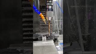 Pecking with rapid out CNC Drilling. |
|
Interesting. I'm getting ready to cut out an AR10 lower on my Tormach. Was working on the CAM in Fusion. I'll download yours and compare to what I come up with as a sanity check. I'm not sure I would have thought to use the mag catch slot as the work offset origin. It's certainly an easy feature to probe in both setups so it makes sense (as long as your probe ball fits). I was going to put a ground pin in the rear (or maybe front) upper attachment points and indicate off that, the mag catch slot is easier for sure. |
|
Quoted: Interesting. I'm getting ready to cut out an AR10 lower on my Tormach. Was working on the CAM in Fusion. I'll download yours and compare to what I come up with as a sanity check. I'm not sure I would have thought to use the mag catch slot as the work offset origin. It's certainly an easy feature to probe in both setups so it makes sense (as long as your probe ball fits). I was going to put a ground pin in the rear (or maybe front) upper attachment points and indicate off that, the mag catch slot is easier for sure.  
|
|
Quoted: What's your Y origin reference point in those two pics? Hard to tell. X (center of slot) and Z (top and side surfaces) seem pretty obvious. 
|
|
Quoted: I am happy to email the fusion file or share the link if you want me to email so you can compare yours. I wish I had a Tormach! I have the TTS system so I pretend lol. I did change mine to not cut the pocket in helical steps and it gave a better finish. https://www.ar15.com/media/mediaFiles/289319/CAM-3378534.png https://www.ar15.com/media/mediaFiles/289319/FinishPass-3378535.png That would be sweet for sure. I'd appreciate that. PM inbound with my email address. I've been enjoying my Tormach a lot. It's primarily used to make pocket knives. They are great tools if you work within their limits. |
|
Quoted: That would be sweet for sure. I'd appreciate that. PM inbound with my email address. I've been enjoying my Tormach a lot. It's primarily used to make pocket knives. They are great tools if you work within their limits. |
|
Quoted: Very helpful. If you have the 3D model already in Fusion it would be pretty easy to utilize it as a tool to cut blocks, which could then be 3D printed as a holding fixture. |
|
Quoted: This interests me very much. You don't happed to have a youtube vid link or anything on that process do you? I do have the 3d model for fusion if anyone else needs it A lot of how you model it depends on the desired end result. Do you want soft jaws or a fixture that repeat position accurately in a CNC machine for multiple parts or do you want a set of plastic blocks that get you going quickly and will be close enough but will wear out if you're doing a lot of parts. Do you want a soft jaw that fits your vise and clamps on both sides of the part, or do you want a fixture plate that the part can be bolted to. These questions all play into how you would go about designing the fixture in CAD. Depending on the desire result you could either 3d print the blocks or machine them from aluminum. Machined blocks if you need accurate repeatability for a lot of parts, 3d printed blocks if you're only doing one or two and the blocks repeat position good enough for your given project. I cut soft jaws for my vises to hold some of my knife parts. Attached File Attached File One way is to just create a block and subtract the solid body from it to form a negative of the part. Then alter the new "negative" of your part so that the part can be inserted into the block. This is not as easy on a complicated part like a lower. There are a lot of items that would need to be cleaned up to make a nice negative soft jaw. Certainly possible, but would take some CAD time. Another way is to draw a sketch parallel to the side of your model, draw in the outline of the "pillars" you'd want to hold your part and project the support pillars from your sketch to the various planes of the part. I did that as a quick example here for you. You can see I chose 3 spots to project supports onto the side of the receiver. I just picked some flat spots that would support the part well. I used the grip mount area as the index in this situation because if the part would be pressed hard down against that pillar it will set the X and Z axis. The Y axis would be set by the fixed jaw of the vise. This was just a quick and dirty example, so I would put some more thought into it if I was going to produce soft jaws like this. For a production fixture, I'd probably find 2 points for each axis to fully restrain it and remove any points that might not index properly. Maybe these pics will help explain how I did it. Attached File Attached File Attached File Attached File |
|
Quoted: A lot of how you model it depends on the desired end result. Do you want soft jaws or a fixture that repeat position accurately in a CNC machine for multiple parts or do you want a set of plastic blocks that get you going quickly and will be close enough but will wear out if you're doing a lot of parts. Do you want a soft jaw that fits your vise and clamps on both sides of the part, or do you want a fixture plate that the part can be bolted to. These questions all play into how you would go about designing the fixture in CAD. Depending on the desire result you could either 3d print the blocks or machine them from aluminum. Machined blocks if you need accurate repeatability for a lot of parts, 3d printed blocks if you're only doing one or two and the blocks repeat position good enough for your given project. I cut soft jaws for my vises to hold some of my knife parts. https://www.ar15.com/media/mediaFiles/59685/Photo_May_07_2024__10_18_41_PM_jpg-3386525.JPG https://www.ar15.com/media/mediaFiles/59685/Photo_Jun_14_2024__1_36_19_PM_jpg-3386532.JPG One way is to just create a block and subtract the solid body from it to form a negative of the part. Then alter the new "negative" of your part so that the part can be inserted into the block. This is not as easy on a complicated part like a lower. There are a lot of items that would need to be cleaned up to make a nice negative soft jaw. Certainly possible, but would take some CAD time. Another way is to draw a sketch parallel to the side of your model, draw in the outline of the "pillars" you'd want to hold your part and project the support pillars from your sketch to the various planes of the part. I did that as a quick example here for you. You can see I chose 3 spots to project supports onto the side of the receiver. I just picked some flat spots that would support the part well. I used the grip mount area as the index in this situation because if the part would be pressed hard down against that pillar it will set the X and Z axis. The Y axis would be set by the fixed jaw of the vise. This was just a quick and dirty example, so I would put some more thought into it if I was going to produce soft jaws like this. For a production fixture, I'd probably find 2 points for each axis to fully restrain it and remove any points that might not index properly. Maybe these pics will help explain how I did it. https://www.ar15.com/media/mediaFiles/59685/Screenshot_2024-11-22_160746_jpg-3386514.JPG https://www.ar15.com/media/mediaFiles/59685/Screenshot_2024-11-22_160833_jpg-3386515.JPG https://www.ar15.com/media/mediaFiles/59685/Screenshot_2024-11-22_160819_jpg-3386516.JPG https://www.ar15.com/media/mediaFiles/59685/Screenshot_2024-11-22_160803_jpg-3386518.JPG 
|


Here is a Glock I just did if anyone wants to see a rough video from a noob. Milling a Glock Slide for a Red Dot. |
|
Quoted: Thank you @Reubjames! I made me a good holder for doing both top and side work. I have to cut it now to see if I nailed it or not. It took me waaaaaaay too long to design, I suck lol. https://www.ar15.com/media/mediaFiles/289319/ARHolder-3404545.png Hey that looks good to me. Glad to help. I'll have to make some like that for AR10 lowers. I can 3d print you a set if you shoot the f3d file over but if you plan on doing more than one, machining them from aluminum is what I'd go with. I've used 3d printed soft jaws for non-critical operations like engraving serial numbers on a bunch of parts. If the dimensions are off a bit, no big deal there but I don't think I'd personally trust them for precision work, too squishy. |
|
Quoted: Here is a Glock I just did if anyone wants to see a rough video from a noob.  https://www.youtube.com/watch?v=5x-8qota88Y https://www.youtube.com/watch?v=5x-8qota88YHeck yeah. I've got a pair of P80 Gen 3 G19 clones for my two sons. I'll be cutting those for them eventually. I need to get my mill back up and running. My x axis servo died a few weeks ago, new servo should be in next week. Knife orders starting to pile up. |
|
Quoted: Hey that looks good to me. Glad to help. I'll have to make some like that for AR10 lowers. I can 3d print you a set if you shoot the f3d file over but if you plan on doing more than one, machining them from aluminum is what I'd go with. I've used 3d printed soft jaws for non-critical operations like engraving serial numbers on a bunch of parts. If the dimensions are off a bit, no big deal there but I don't think I'd personally trust them for precision work, too squishy. AR10 Please The PPS-CF10 filament once annealed is great. I have seen some say it doesn't handle shock well, but yet I have seen large handbells printed from it. The bell is used in Fiberon's booth for demo so I know it has been abused. |
|
Quoted: AR10 Please The PPS-CF10 filament once annealed is great. I have seen some say it doesn't handle shock well, but yet I have seen large handbells printed from it. The bell is used in Fiberon's booth for demo so I know it has been abused. I'll have to give some a try. |
|
Quoted: Heck yeah. I've got a pair of P80 Gen 3 G19 clones for my two sons. I'll be cutting those for them eventually. I need to get my mill back up and running. My x axis servo died a few weeks ago, new servo should be in next week. Knife orders starting to pile up. |
|
Quoted: I just bartered some labor for 3 servos with drivers to upgrade my stepper motors and cannot wait to do it. I am limited to .001 movements now which is problematic when the read out is at .0004 so I have to skip to the closest thousandth. The servos should let me move in 10 thousands...I hope lol. Nice. What servos are you getting? |
|
Quoted: That looks like something that could be easily 3D Printed especially with some good materials. Might take a few iterations to get the dimensions correct. late to the party, but here is the design i modified from an earlier design, and updated for milling vs routering. https://www.thingiverse.com/thing:6655978  I use one side only when doing the side work, rather than using the holes as a template, since the mill has better accuracy - those holes are essentially a hold over from that period. i used ABS in prior designs, but find PETG to be heat resistant enough with better dimensional accuracy nowadays. |
|
Quoted: late to the party, but here is the design i modified from an earlier design, and updated for milling vs routering. https://www.thingiverse.com/thing:6655978 https://cdn.thingiverse.com/assets/d0/fc/b7/c4/40/large_display_1f9735c6-3696-4cf1-aaf7-faf2e9d08ffa.jpg I use one side only when doing the side work, rather than using the holes as a template, since the mill has better accuracy - those holes are essentially a hold over from that period. i used ABS in prior designs, but find PETG to be heat resistant enough with better dimensional accuracy nowadays. Thank you for sharing those files. Every little bit helps when taking the step into this. BTW that Vevor decal kills me on the vice. |
|
Quoted: Thank you for sharing those files. Every little bit helps when taking the step into this. BTW that Vevor decal kills me on the vice. Quoted: Quoted: late to the party, but here is the design i modified from an earlier design, and updated for milling vs routering. https://www.thingiverse.com/thing:6655978 https://cdn.thingiverse.com/assets/d0/fc/b7/c4/40/large_display_1f9735c6-3696-4cf1-aaf7-faf2e9d08ffa.jpg I use one side only when doing the side work, rather than using the holes as a template, since the mill has better accuracy - those holes are essentially a hold over from that period. i used ABS in prior designs, but find PETG to be heat resistant enough with better dimensional accuracy nowadays. Thank you for sharing those files. Every little bit helps when taking the step into this. BTW that Vevor decal kills me on the vice. Yeah.. its a vevor brand.. maybe i am supposed to remove it? Idk.. documentation was in chinese.  |
|
Quoted: Yeah.. its a vevor brand.. maybe i am supposed to remove it? Idk.. documentation was in chinese. |
|
Quoted: late to the party, but here is the design i modified from an earlier design, and updated for milling vs routering. https://www.thingiverse.com/thing:6655978 https://cdn.thingiverse.com/assets/d0/fc/b7/c4/40/large_display_1f9735c6-3696-4cf1-aaf7-faf2e9d08ffa.jpg I use one side only when doing the side work, rather than using the holes as a template, since the mill has better accuracy - those holes are essentially a hold over from that period. i used ABS in prior designs, but find PETG to be heat resistant enough with better dimensional accuracy nowadays. Awesom going to download this and use it in the future. |
|
Quoted: late to the party, but here is the design i modified from an earlier design, and updated for milling vs routering. https://www.thingiverse.com/thing:6655978 https://cdn.thingiverse.com/assets/d0/fc/b7/c4/40/large_display_1f9735c6-3696-4cf1-aaf7-faf2e9d08ffa.jpg I use one side only when doing the side work, rather than using the holes as a template, since the mill has better accuracy - those holes are essentially a hold over from that period. i used ABS in prior designs, but find PETG to be heat resistant enough with better dimensional accuracy nowadays. Dude, nice. Thanks for sharing. Very handy. I printed some other ones out I found but wasn't really thrilled with them. Looks like you did 5 layer shells. What about top and bottom layer count? And layer heights? I'm assuming .4 nozzle? |
|
Quoted: Dude, nice. Thanks for sharing. Very handy. I printed some other ones out I found but wasn't really thrilled with them. Looks like you did 5 layer shells. What about top and bottom layer count? And layer heights? I'm assuming .4 nozzle? Yeah i had several billet lowers so this kept evolving to accomodate different non standard things in addition to milspec. I dont recall the settings - but yes you would want at lest 5 walls and 50% infill for rigidity. .4 will work fine yes. |


|
Quoted: Just noticed this discussion so I'm a little late. I built an 80% fixture several years ago, here are some pics and drawings. I have them available in Autocad and Solidworks as well. https://i.imgur.com/5lMBLGO.jpg https://i.imgur.com/XRxIHfF.jpg https://i.imgur.com/12Bb4WJ.jpg https://i.imgur.com/CMUDIQy.jpg https://i.imgur.com/pNVgJeF.jpg Dm sent |
|
Quoted: Just noticed this discussion so I'm a little late. I built an 80% fixture several years ago, here are some pics and drawings. I have them available in Autocad and Solidworks as well. https://i.imgur.com/5lMBLGO.jpg https://i.imgur.com/XRxIHfF.jpg https://i.imgur.com/12Bb4WJ.jpg https://i.imgur.com/CMUDIQy.jpg https://i.imgur.com/pNVgJeF.jpg |
|
Quoted: This works on AR-15 and AR-10 if using the WCS I have made. (Make sure to set Z on the places you are milling, x and y is where is you see the dots, I use a probe to indicate centers. Steps Broken Up in parts: ... 1 - roughing pocket.nc 2 - finishing pocket.nc 3 - trigger slot.nc A - Center Drilling.nc (Pecking) B - Small Holes.nc (Pecking) C - Large Hole.nc (Pecking) Any recommendations for a parser/visualizer/editor I can use to remove the right inside hump? What can I say - I'm a pocket purist.
|
|
Quoted: Any recommendations for a parser/visualizer/editor I can use to remove the right inside hump? What can I say - I'm a pocket purist.  Roughing: Click To View SpoilerFinishing: Click To View Spoiler |
|
Quoted: Here is that pocket cut to clean the inner walls: (I changed to a 7/16 End Mill for Roughing then a 3/8 for finishing.) https://www.ar15.com/media/mediaFiles/289319/Pocket-3434286.png Roughing: Finishing: |
|
OP are you just loading a lower model into fusion then creating stock big enough to cover the pocket and applying a pocket clearout to that? I need to do a much different speeds and feeds with a benchtop cnc router than for a benchtop cnc mill so i need to do my own setup - just wondering how you setup the stock? |
|
Quoted: OP are you just loading a lower model into fusion then creating stock big enough to cover the pocket and applying a pocket clearout to that? I need to do a much different speeds and feeds with a benchtop cnc router than for a benchtop cnc mill so i need to do my own setup - just wondering how you setup the stock? 
|
|
Quoted: Finally got my servos back up and running so I may tackle my AR10 lower in the next few weeks. Got a bunch of knives I need to finish first though which will probably take priority. Hope I don't have to back burner this project too much longer. |
|
Quoted: Good deal. I just broke mine =( Upgraded my BLDC to a Servo on the spindle and hooking up the speed control to acorn I grounded it out and fried the controller. Ouch, that sucks for sure. You going to go back with Acorn again? I've been eyeballing one of those Masso controllers for a CNC lathe conversion. |
|
Quoted: Ouch, that sucks for sure. You going to go back with Acorn again? I've been eyeballing one of those Masso controllers for a CNC lathe conversion. |
|
Quoted: That is correct. I can send you the fusion file so you can adjust if easier, just email me. https://www.ar15.com/media/mediaFiles/289319/ARFusion-3446758.png OG I had to completely re-work it for my CNC Router (just cant run the same kind of engagement, larger mills etc) - but it was a good learning experience and super helpful to see how you had it setup, cheers! eta: for ref, you stated "10:10 mins on pockets and 1:54 mins on drills.".. on my CNC router, 2:04:00 (2 HOURS 4 minutes) for clearning, 22 minutes for finishing and the trigger hole, and about 2 minutes per side on drilling and clearing, using a 1/4"mill to mill out the 3/8 hole for the safety. just shows how much more effective a CNC mill is than a CNC router
|
|
Quoted: OG I had to completely re-work it for my CNC Router (just cant run the same kind of engagement, larger mills etc) - but it was a good learning experience and super helpful to see how you had it setup, cheers! eta: for ref, you stated "10:10 mins on pockets and 1:54 mins on drills.".. on my CNC router, 2:04:00 (2 HOURS 4 minutes) for clearning, 22 minutes for finishing and the trigger hole, and about 2 minutes per side on drilling and clearing, using a 1/4"mill to mill out the 3/8 hole for the safety. just shows how much more effective a CNC mill is than a CNC router My next project is making my own 2011 Frame from scratch out of Titanium. I have the design done and the cam almost done then will probably do in Aluminum first. In the grand scheme I'm a newbie. Ive been doing this about 2 years but only just learned I need to compensate for the variance in my end mill diameters. I assumed they were perfectly sized as advertised but they are not so I'm going to do easy plunges on all and measure to see unless I find and easier way to do it. What I was doing was designing everything exact to specs then using stock to leave to go over anywhere from a few ten thousands to a few thousands depending what I'm doing but I always do a test part in aluminum to get that figure. I think perhaps my issue all along is end mill diameters being off. Acorn has comp for it. |
| I am watching the Milo Mill and and Rat Rig mill beta. I am liking what I am seeing out of the RR with a 2.2kw spindle. I would upgrade to a an ISO20 tool holders so I can make use of a tool hanger. It's large enough to do about anything I would be interested in. |