|
Posted: 10/24/2018 3:05:20 PM EDT
NOTE: This is an open source project - I'm not selling anything, all plans will be made available free of change. Just tapping ARFCOMs SMEs on the F/A-18C and kinda proud of what I'm doing.
Link to original thread in archives: https://www.ar15.com/forums/general/OpenHornet-F-A-18C-1-1-Replica-SimPit-WIP-/5-2072333/ So, this project has progressed so, so far over the past six months. Still haven't built anything yet, just getting design hammered down. I was curious if anyone here might have some good front, side, top views of the SJU-23 ejection seat? I'm having a very hard time finding information to extrapolate dimensions from. Also, approximately how much force is required to actuate the main ejection handle and the seat arming lever? Hope you three don't mind me tagging you - you've been incredible helps on some of the questions I have had: @FlyNavy75 @Sixtigers @TufelByte Anyways, here are the renders of the project, current as of today. 


|
|
|
|
[#1]
Straight from the big book:
20-40lbs to unseat the handle from the housing and a continued 30-60lb pull to fire the initiators and send the seat flying. Sorry, no pics. |
|
|
|
[#2]
Quoted:
Straight from the big book: 20-40lbs to unseat the handle from the housing and a continued 30-60lb pull to fire the initiators and send the seat flying. Sorry, no pics. |
|
|
|
[#3]
its going to be nice.
mine's much simplier |
|
|
|
[#4]
I can’t get you pics. Security protocols here.
Might be able to get you diagrams. Would that help? |
|
|
|
[#5]
Quoted:
I can't get you pics. Security protocols here. Might be able to get you diagrams. Would that help? |
|
|
|
[#6]
That's freaking cool.
|
|
|
|
[#7]
Quoted:
That's freaking cool. |
|
|
|
[#8]
What exactly are you looking for? You're close. Some switches are in odd positions in those pics but I'm sure you probably know that already.
Do you plan on finding used parts on the market or building this from scratch? How do you plan on programing the displays? |
|
|
|
[#9]
Looks fantastic. The stick and throttle?
|
|
|
|
[#10]
So much want.
|
|
|
|
[#11]
At least you showed us peasants what's up Seriously though, awesome work OP! Keep us tuned in. Maybe a YouTube video once it's all up and running? |
|
|
|
[#12]
Quoted:
What exactly are you looking for? You're close. Some switches are in odd positions in those pics but I'm sure you probably know that already. Do you plan on finding used parts on the market or building this from scratch? How do you plan on programing the displays? The switch positions are irrelevant in the model, just so that the switch positions are oriented properly electrically speaking. This will be a total scratch build. Displays will be driven via export from DCS, and streamed to RPIs, which will hook up to the displays (minimizing the number of display ports from the PC running the sim.) |
|
|
|
[#13]
Do I have to memorize a 1000 page manual just to fly the damn thing?
|
|
|
|
[#14]
Quoted:
Do I have to memorize a 1000 page manual just to fly the damn thing? If you want to do it properly you better know a few things though |
|
|
|
[#15]
Quoted:
Looks fantastic. The stick and throttle? We got our hands on a real inboard throttle grip, and have duplicated it in a model, and have been able to extrapolate the outboard grip from that and other references. I'll be taking the reference model (once finished up) and making it into something manufacturable, and I'll finish out the throttle assembly at that time. I'm investigating various COTS solutions for rudder pedals with some printed pedals to replace what's on there. Looking very hard at the MFG Crosswinds. |
|
|
|
[#16]
Quoted:
Do I have to memorize a 1000 page manual just to fly the damn thing? |
|
|
|
[#17]
Quoted:
Basically any square on views of the seat, weather photographs or diagrams. Also, any views or diagrams of the stick, square on past what's in the -000 NATOPS. The switch positions are irrelevant in the model, just so that the switch positions are oriented properly electrically speaking. This will be a total scratch build. Displays will be driven via export from DCS, and streamed to RPIs, which will hook up to the displays (minimizing the number of display ports from the PC running the sim.) https://www.digitalcombatsimulator.com/en/products/planes/hornet/ 
|
|
|
|
[#18]
SJU-17(series) by the way
IM sent. |
|
|
|
[#19]
Quoted:
Do I have to memorize a 1000 page manual just to fly the damn thing? |
|
|
|
[#20]
Quoted:
https://www.AR15.Com/media/mediaFiles/413021/20181025_004326_jpg-716292.JPG At least you showed us peasants what's up Seriously though, awesome work OP! Keep us tuned in. Maybe a YouTube video once it's all up and running? |
|
|
|
[#21]
Quoted:
Just in case others aren't familiar with DCS: https://www.digitalcombatsimulator.com/en/products/planes/hornet/ https://i.postimg.cc/jSDVQChk/dcsf18.png Quoted:
Quoted:
Basically any square on views of the seat, weather photographs or diagrams. Also, any views or diagrams of the stick, square on past what's in the -000 NATOPS. The switch positions are irrelevant in the model, just so that the switch positions are oriented properly electrically speaking. This will be a total scratch build. Displays will be driven via export from DCS, and streamed to RPIs, which will hook up to the displays (minimizing the number of display ports from the PC running the sim.) https://www.digitalcombatsimulator.com/en/products/planes/hornet/ https://i.postimg.cc/jSDVQChk/dcsf18.png |
|
|
|
[#22]
Quoted: Holy crap.... |
|
|
|
[#23]
That looks great. I can't wait to see the progress.
|
|
|
|
[#24]
That looks amazing. However have you considered the VR alternative? I just fired up DCS with VR for the first time this week and am blown away by the feeling of actually sitting in a tiny cockpit and looking out over vast distances. This is only going to get better as the headsets improve (I'm using a Rift). Even a full dome over a physical cockpit wouldn't convey the depth of VR.
Of course the trade off against your cockpit is the tactile feedback of actually hitting real switches assuming you wire those up to the sim somehow. |
|
|
|
[#25]
Quoted:
That looks amazing. However have you considered the VR alternative? I just fired up DCS with VR for the first time this week and am blown away by the feeling of actually sitting in a tiny cockpit and looking out over vast distances. This is only going to get better as the headsets improve (I'm using a Rift). Even a full dome over a physical cockpit wouldn't convey the depth of VR. Of course the trade off against your cockpit is the tactile feedback of actually hitting real switches assuming you wire those up to the sim somehow. My pie in the sky dream is AR. Real world pit and VR "out-the-window". |
|
|
|
[#26]
Quoted:
Basically any square on views of the seat, weather photographs or diagrams. Also, any views or diagrams of the stick, square on past what's in the -000 NATOPS. The switch positions are irrelevant in the model, just so that the switch positions are oriented properly electrically speaking. This will be a total scratch build. Displays will be driven via export from DCS, and streamed to RPIs, which will hook up to the displays (minimizing the number of display ports from the PC running the sim.) Quoted:
Quoted:
What exactly are you looking for? You're close. Some switches are in odd positions in those pics but I'm sure you probably know that already. Do you plan on finding used parts on the market or building this from scratch? How do you plan on programing the displays? The switch positions are irrelevant in the model, just so that the switch positions are oriented properly electrically speaking. This will be a total scratch build. Displays will be driven via export from DCS, and streamed to RPIs, which will hook up to the displays (minimizing the number of display ports from the PC running the sim.) Very cool project by the way. |
|
|
|
[#27]
Quoted: How do you plan to make the panels? Are you going to back light them? Are you trying to get all of the displays to indicate correctly? All of the switches function? Very cool project by the way. Backlighting: We opted to not backlight with the initial version of this pit. It adds a huge cost/complexity. To do it right, it would triple the cost of every panel. That said, the electronics reserve a 12v PWM output for future backlighting. We arent going to try to get all the displays and gauges and switches to work. They will. |
|
|
|
[#28]
Quoted:
Thanks! The panels are .125 acrylic backplate, with an .1875 acrylic light plate, and a .0625 legend plate. The legend plate is a two ply white on black engravable plastic. Light plate and legend plate will be bonded with Weld-On #4 (or equivalent), painted flat black, and engraved. We opted for .125 acrylic Backplates vs. 0625 aluminum due to limitations of most hobby grade CNCs. Backlighting: We opted to not backlight with the initial version of this pit. It adds a huge cost/complexity. To do it right, it would triple the cost of every panel. That said, the electronics reserve a 12v PWM output for future backlighting. We arent going to try to get all the displays and gauges and switches to work. They will. |
|
|
|
[#29]
Quoted: Are You going to make some classical gauges digital ? Like the pressure gauge ? Is it going to be a needle or the image of a needle ? |
|
|
|
[#30]
Quoted:
Oh absolutely. And detailed plans on how to make your own. |
|
|
|
[#31]
Picked up the Warthog HOTAS last week. My TRP Peddles and Cougar MFD's came in today. TrackIR5 Pro is being delivered on Saturday.
Now trying to get everything to work together. LOL Windows 10 is a pain in the ass. |
|
|
|
[#32]
Quoted:
Stick is very much WIP. We still are having a hard time finding enough pictures or diagrams of the stick grip to accurately replicate it, so we might be stuck waiting for Thrustmaster to release their F/A-18 grip for the Warthog. Mechanism is currently undergoing a redesign to simplify it and get the forces correct. We got our hands on a real inboard throttle grip, and have duplicated it in a model, and have been able to extrapolate the outboard grip from that and other references. I'll be taking the reference model (once finished up) and making it into something manufacturable, and I'll finish out the throttle assembly at that time. I'm investigating various COTS solutions for rudder pedals with some printed pedals to replace what's on there. Looking very hard at the MFG Crosswinds. 
|
|
|
|
[#33]
Pretty damn cool OP.
Out of curiosity, what sort of budget are you looking at for something like this? I can't afford it, but it's nice to dream 
|
|
|
|
[#34]
Quoted:
Holy crap.... Quoted:
Quoted:
Quoted:
Basically any square on views of the seat, weather photographs or diagrams. Also, any views or diagrams of the stick, square on past what's in the -000 NATOPS. The switch positions are irrelevant in the model, just so that the switch positions are oriented properly electrically speaking. This will be a total scratch build. Displays will be driven via export from DCS, and streamed to RPIs, which will hook up to the displays (minimizing the number of display ports from the PC running the sim.) https://www.digitalcombatsimulator.com/en/products/planes/hornet/ https://i.postimg.cc/jSDVQChk/dcsf18.png 
 DCS: F-14 - Pre-Order / Gameplay Reveal Trailer - OUT NOW! |
|
|
|
[#35]
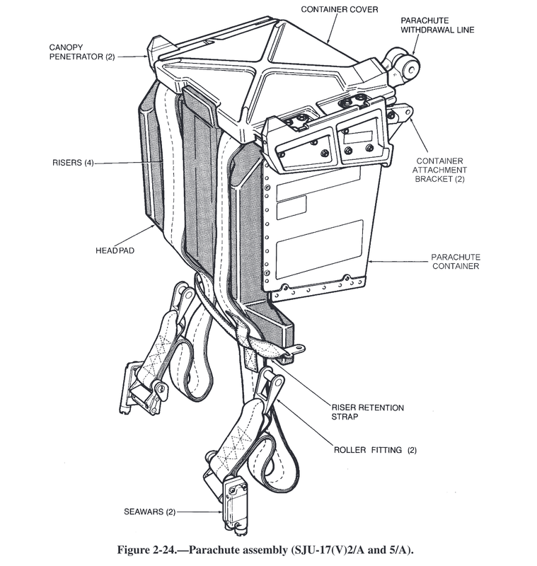
Just took a quick look through the Super Hornet and Growler NAVTOPS 100 & 200, no seat diagrams like the one you wanted. Dug these up however in another manual.
If you figure the harness straps are roughly 2" you can probably guess, or come close to angles and dimensions from there. 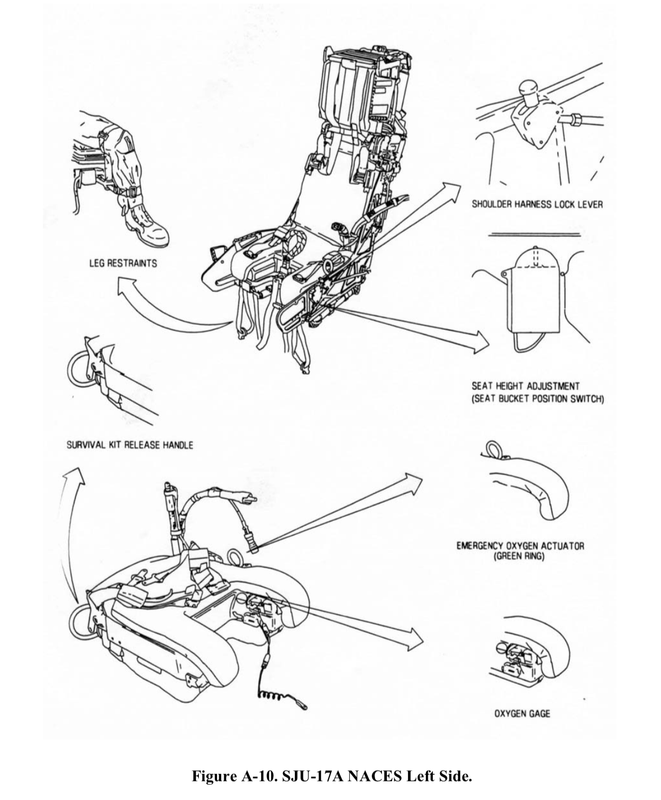


|
|
|
|
[#36]
Quoted:
Pretty damn cool OP. Out of curiosity, what sort of budget are you looking at for something like this? I can't afford it, but it's nice to dream |
|
|
|
[#37]
|
|
|
|
[#38]
I get to fly a real Hornet simulator once a year or so.
A lot of fun. And this looks pretty cool. Great project, you have a lot of patience!! |
|
|
|
[#39]
How can I help you with grip controller measurements? Short of actually sending you one. Close-up photos with a ruler?
|
|
|
|
[#40]
Impressive undertaking.
|
|
|
|
[#41]
Quoted:
How can I help you with grip controller measurements? Short of actually sending you one. Close-up photos with a ruler? |
|
|
|
[#42]
So basically, I need as many images as possible around the object (I took over 100 when I did the throttle grip, but you don't have to go that crazy.) The most important thing is that every part of the model should be visible in at least 3 images, though preferably more. Even/consistent lighting is important. It's also important that the model doesn't move relative to the environment. It would also be helpful if he included an object with known dimensions in the scene so that I can calibrate the size. A ruler could work. If possible, I'd like to get the box with the pinky lever as well.
Here is a little video primer on the process:  Photogrammetry - 3D scan with just your phone/camera |
|
|
|
[#43]
Bad ass!
|
|
|
|
[#44]
Can anyone tell me the MIL-STD for the brake pressure gauge? Cant seem to dig that up anywhere.
|
|
|
|
[#45]
Quoted:
Picked up the Warthog HOTAS last week. My TRP Peddles and Cougar MFD's came in today. TrackIR5 Pro is being delivered on Saturday. Now trying to get everything to work together. LOL Windows 10 is a pain in the ass. |
|
|
|
[#46]
When pulling the parking/emergency brake handle, does it have a hydraulic type resistance to it? Figuring out if I need to throw a gas damper on the shaft.
|
|
|
|
[#47]
@FlyNavy75 @Sixtigers
@TufelByte Also, how much force does it take to rotate or pull the handle off its detents? |
|
|
|
[#48]
Quoted:
When pulling the parking/emergency brake handle, does it have a hydraulic type resistance to it? Figuring out if I need to throw a gas damper on the shaft. |
|
|
|
[#49]
It’s spring tension. About 10 pounds worth.
|
|
|
|
[#50]
Finished the Brake/Emergency Handle mechanism and the brake pressure gauge yesterday. Left console is component complete (minus throttle). Going to start working on modeling the PCBs and start dropping the electronics layer in. Goal on the left/right consoles is have them interface to the rest of the pit with a single USB cable and a single power connection.
|
|
|
 Win a FREE Membership!
Sign up for the ARFCOM weekly newsletter and be entered to win a free ARFCOM membership. One new winner* is announced every week!
You will receive an email every Friday morning featuring the latest chatter from the hottest topics, breaking news surrounding legislation, as well as exclusive deals only available to ARFCOM email subscribers.

AR15.COM is the world's largest firearm community and is a gathering place for firearm enthusiasts of all types.
From hunters and military members, to competition shooters and general firearm enthusiasts, we welcome anyone who values and respects the way of the firearm.

Subscribe to our monthly Newsletter to receive firearm news, product discounts from your favorite Industry Partners, and more.
Copyright © 1996-2024 AR15.COM LLC. All Rights Reserved.
Any use of this content without express written consent is prohibited.
AR15.Com reserves the right to overwrite or replace any affiliate, commercial, or monetizable links, posted by users, with our own.


