|
Posted: 2/15/2010 1:12:01 PM EDT
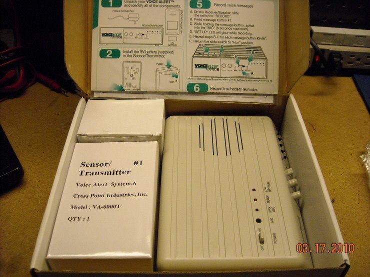
This thread will be about a little gadget I've been playing with for a while. It's this system from Cross Point Industries:

Here's our experimental subject with two Passive-InfraRed (PIR) sensors:: 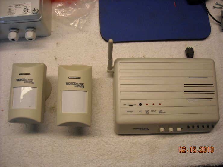
Here's one with the innards exposed: 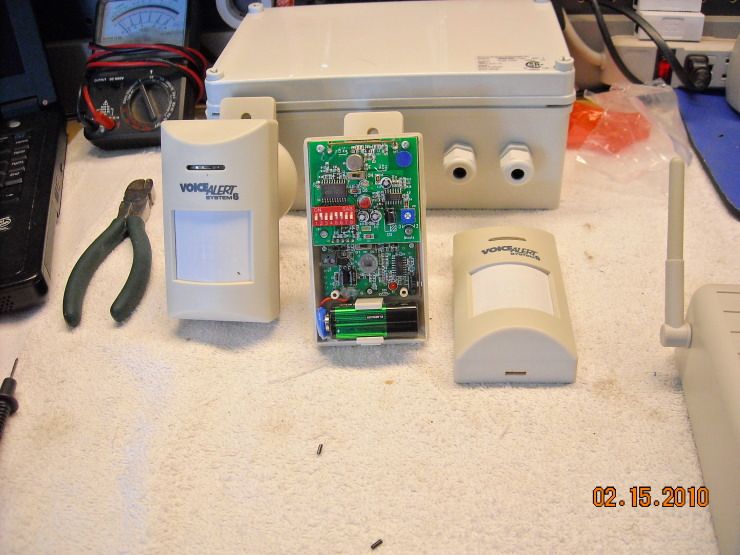
Here's the power supply they send with it. 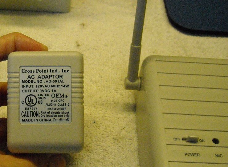
I've been playing with this thing for a while, and will have more to say about it when I've had a chance to write more. It's FAR from a perfect system (the PIRs in particular were disappointing)... but it has potential. More to come. |
|
|
|
[#1]
The PSU they send with the unit can carry about 1A and 9VDC. It doesn't pull nearly that much under normal circumstances:
The Kill-a-Watt says it's pulling about 100mA. It's actually less than that... see below: 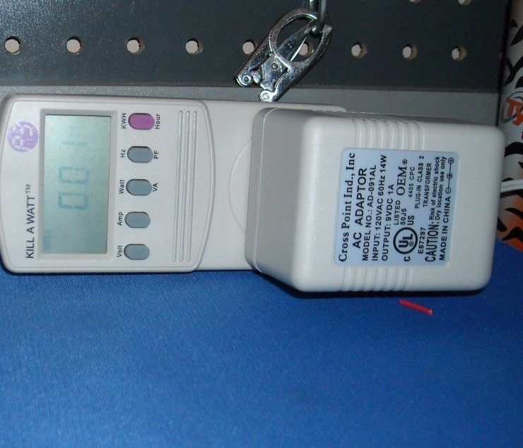
I took an adapter plug with screw-down terminals and measured the amount of current the unit actually draws (minus the inefficiencies of the wall-wart). I used a different 9V transformer, since I didn't want to cut the plug-end off the wall-wart that came with the unit: 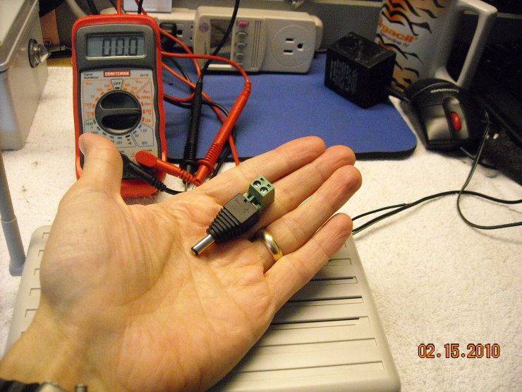
Measuring downstream from the wall-wart, we see it's actually pulling less than 100mA: 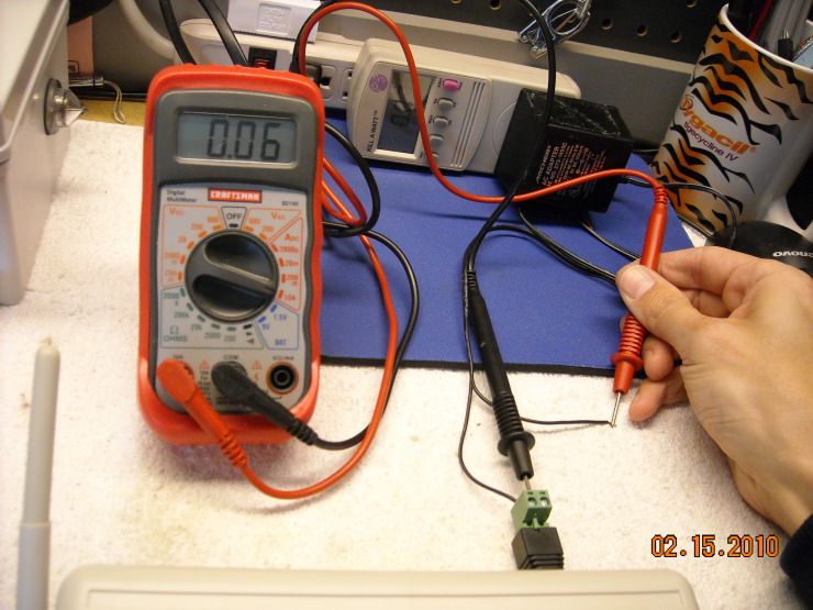
Changing the scale shows that the unit pulls roughly 65mA just sitting there, waiting for one of the sensors to trigger it: 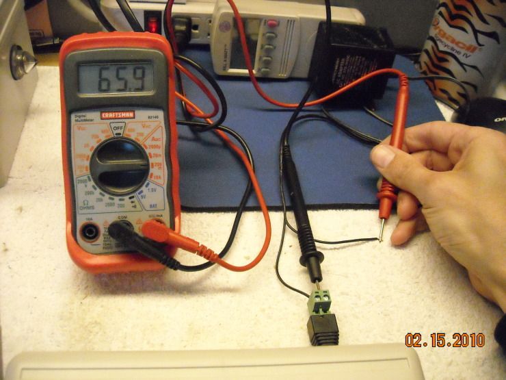
When activated and using the speaker, the current draw roughly doubles: 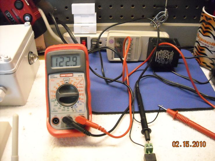
Drops a bit... 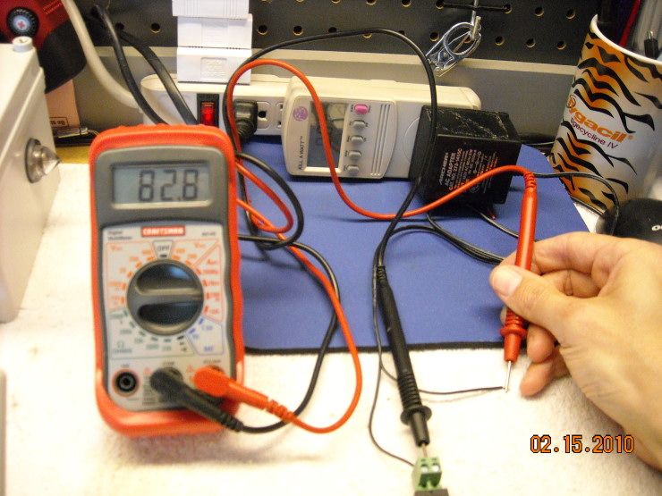
And ends up right back where it started, once finished playing the message you recorded inside it:
This is important, because it gives you an idea how long you might run one of these units on batteries, rather than wall power. |
|
|
|
[#2]
I'm kinda liking this.
I'll watch for your review. edit: I hate 9 volt batteries. 
|
|
|
|
[#3]
I am interested in this. Do you know yet what the frequency is, such as 2.4 ghz ?
It may mess up my camera's which are in the 2.4 ghz area. |
|
|
|
[#4]
Quoted:
I am interested in this. Do you know yet what the frequency is, such as 2.4 ghz ? It may mess up my camera's which are in the 2.4 ghz area. 433.92 MHz |
|
|
|
[#5]
Thanks !
Will you be updating us as you go along ? |
|
|
|
[#6]
Quoted:
Thanks ! Will you be updating us as you go along ? Yes |
|
|
|
[#7]
Tag. I've been looking at this for a while, just haven't really needed to pull the trigger.
|
|
|
|
[#8]
Quoted:
Quoted:
I am interested in this. Do you know yet what the frequency is, such as 2.4 ghz ? It may mess up my camera's which are in the 2.4 ghz area. 433.92 MHz Hmmmmm.... I bet a 440 HT ham radio would work as a remote receiver. |
|
|
|
[#9]
yep tag
|
|
|
|
[#10]
TAG?
|
|
|
|
[#11]
A bit more about the sensors that come with the unit.
Here is a close-up of the innards of the PIR. There are two switches on the PCB. The bottom one (circled) actually turns the sensor off and on. The upper one turns the indicator light (indicating that you've been detected) off and on. The indicator light is useful for mounting/testing/aiming the PIR, but should otherwise be left off to save the battery. There is a small blue-and-white potentiometer on the PCB as well (right, middle of the circuit board). This sets the reset time for the sensor to alarm again. If you set it for a longer interval, you'll greatly increase your battery life... you can easily get 6mo out of a single 9V battery. The PIRs don't work as well as I'd hoped. I've mounted them indoors and outdoors, and your outdoor mounting options are limited, because these sensors are prone to false alarms. You cannot mount them in direct sunlight, but even when mounted in a cool, shaded location, they still have a tendency to alert when nothing is happening. Even shadows will set them off. I tested this with multiple sensors, and had the same false-alarm problem. It also happened regardless of whether it was day or night. It even happened when I had put the little restrictor mask inside the PIR to narrow the detection beam. Despite the fact that these PIRs are fairly water-resistant (they have a very nice gasket around the removable face that seals them well), they just false-alarm too much... so consider putting them indoors (or inside a detached garage or vehicle), but outdoors may drive you crazy with false alarms. This is a major strike against the system. Most high-quality motion sensors have at least dual-sensor technology. That is, they have a passive pyroelectric sensor element (Voice Alert's PIRs have that... it's the little component that detects your body heat), but higher-end sensors also have a ultrasonic or radar-type sensor, which the Voice Alert sensor lacks.. A unit with dual sensors will only alarm when it gets a positive hit on BOTH the pyroelectric sensor, and the radar. (Explanation of the relevant technology here.). I'm quite sure the designers of these sensors omitted the radar/ultrasonic doppler sensor to conserve battery life. If you had to power a radar element, that 9V battery would die in short order. 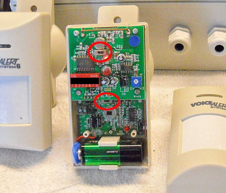
Fortunately, there are other sensors. I'll get to those in my next update. |
|
|
|
[#12]
Which brings me to the more interesting sensors that you can get with this system... the vibration sensors and/or generic transmitters:
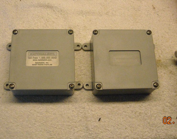
The two gray boxes you see are water-tight NEMA enclosures. The one on the left was an Ebay find.... there's apparently a system out there for swimming pools designed to detect motion, like when a child falls in... and it has a "vibration sensor" that attaches to a webbing rig that goes over the pool surface. It looked almost identical to the actual Cross-Point Industries motion sensor that I already had... so much so, that I bought it... just on a hunch. The hunch turned out to be right. The "Katchalert" motion sensor is actually detectable by the Voice Alert System 6's base unit, and it only cost me 20 bucks or so... far less than the 70$ you pay for the Cross-Point detector. Anyway... the innards are also very similar. You'll note that there is a little silver-colored cylinder in the lower left of the PCB on the left-handed "Katchalert" sensor, and a similar silver cylinder attached to the right-handed PCB with wire. 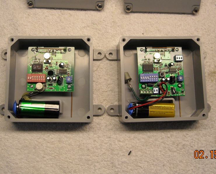
That short little cylinder is the vibration sensor... it's a micro-ball motion sensor element (link here ): 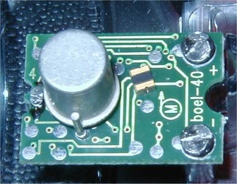
This, I believe, is the real potential of this system. That little sensor element can be removed, and replaced/rewired to take virtually any sort of sensor. You could use that little box as the transmitter element, and wire it up to a reed switch, a contact switch, a pressure switch, a relay, a water sensor (to warn you if your sump pump dies)... the options are almost endless. Or... you could simply leave it as-is, and use it as it was designed. It still has utility in that way, and here is an example: 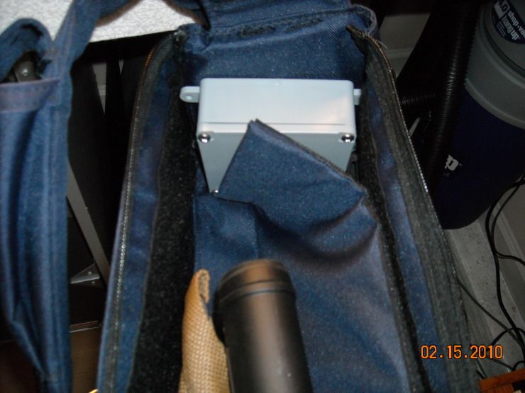
That is one of the transmitters inside my Cav-Arms discrete rifle bag. Any time that bag is moved, it sends a signal to the base unit, and plays a pre-recorded message. Recently, my neighborhood has suffered a rash of automotive burglaries... so I have also placed one of those transmitters inside the center console of my truck, with a few dollars in cash visible underneath it. No teenage auto burglar is going to leave cold, hard cash sitting there, so they'll move the unit in order to grab the money. The possibilities are virtually endless. |
|
|
|
[#13]
What also strikes me about this base unit is how simple the signaling method is... Look again at the sensors:
What you want to pay attention to are the banks of Dip Switches. They're in red on the one sensor, and blue on the other, and there are eight switches in each bank. The dip switches are used to set each sensor's numeric "identity," and they create a binary number, based on whether the switch is on, or off. In the example below, you see that the second Dip switch is set to "on," and the remainder are set to "off." That gives the device an ID# of 2. Each dip switch gives you a value, going from left to right. They are 1, 2, 4, 8, 16, 32, 64, and 128 (in the case of an eight-bit binary number). The values are additive, so having the first AND second dip switch set to "on" would give you an ID# of 3. To have an ID# of four, you'd set the third dip switch to on, and all the other to off, and so forth. This enables you to set the device with any ID# from 1 to 256 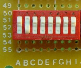
Which brings me to this device: 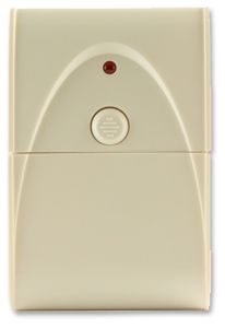
If one reads the description of this device here (it's made by a completely different company: Dakota Alert), one notices something interesting: # Frequency 433.92 MHz
# Code Combinations 256 That's right... it's on the same frequency, and has the same number of code combinations. In fact, I'm willing to bet a nice cold beer that there's a bank of dip switches inside that Dakota Alert transmitter... probably just like the set inside the Voice Alert sensors... opening up the possibility that these devices might actually talk to one another. |
|
|
|
[#14]
G-M, why not see if you can find the FCC id on thees units and go to the FCC site and look up the schematic and a lot of other tech info abt the units.
Also, the 8 bit digital codes are common to remote devices to identify them uniquely, and the problem for intercompatability arises in how the data is transmitted, timings and the sequence of the 1's and 0's, and make for an infinite number of possible codes. Won't hurt to try and don't overlook trying the complement of the code. |
|
|
|
[#15]
Also, if you really get into this and have a scope, probe around in the transmitters and you will find the code as it comes out on a pin on the processor chip and goes to modulate the transmitter.
Actually easy to do. You will see exactly what the code is. You can also do it with a scanner that tunes the freq and a spec an. Also, you can probably hear it on an AM radio held closely to the xmitter. Many ways to 'read' the code. |
|
|
|
[#16]
I bought a VoiceAlert when gas hit 4 bucks. I park in the driveway. I put the sensor on a tree about 20 feet from my car and got some camo duct tape that virtually matched the maple tree.
I can say it will send a signal to the control unit 60-70 feet through a garage door and two interior walls. Never did have a gas thief, but it foiled some pumpkin stealing utes last Halloween. I had to trim a few limbs near the car, but I haven't been bothered by false alarms in my situation. |
|
|
|
[#17]
Quoted:
Also, if you really get into this and have a scope, probe around in the transmitters and you will find the code as it comes out on a pin on the processor chip and goes to modulate the transmitter. Actually easy to do. You will see exactly what the code is. You can also do it with a scanner that tunes the freq and a spec an. Also, you can probably hear it on an AM radio held closely to the xmitter. Many ways to 'read' the code. The Voice Alert codes actually come through on the computer speakers on my test bench (I like to stream Winamp while I'm tinkering). I haven't tried counting the pulses. There are a bunch of these systems out there... including one by Skylink. I haven't yet found the specific freq information on their sensors, but the model numbers all include "433," which may be a coincidence, but I find interesting, considering the frequency these things all seem to center on 433.92MHz |
|
|
|
[#18]
Quoted:
Quoted:
Quoted:
I am interested in this. Do you know yet what the frequency is, such as 2.4 ghz ? It may mess up my camera's which are in the 2.4 ghz area. 433.92 MHz Hmmmmm.... I bet a 440 HT ham radio would work as a remote receiver. Might work to jam it as well........... |
|
|
|
[#19]
If you look closely, you'll notice that the transmitter boards are exactly the same in those sensors. Not only the vibration sensors, but the PIRs as well.
Look at the close-up pic of the open PIR. The PIRs have two PCBs, and the top PCB (the transmitter board) is identical to the one in the vibration sensor. The lower PCB in the PIR is merely the board that runs the pyroelectric sensor element. This leads one to the possibility of scavenging those transmitter boards from the false-alarm-prone PIRs, and using them for other applications. |
|
|
|
[#20]
Quoted:
If you look closely, you'll notice that the transmitter boards are exactly the same in those sensors. Not only the vibration sensors, but the PIRs as well. Look at the close-up pic of the open PIR. The PIRs have two PCBs, and the top PCB (the transmitter board) is identical to the one in the vibration sensor. The lower PCB in the PIR is merely the board that runs the pyroelectric sensor element. This leads one to the possibility of scavenging those transmitter boards from the false-alarm-prone PIRs, and using them for other applications. 433.92mhz transmitter componets and premade boards are very common and cheap. http://home.att.net/~wzmicro/rf_xmitter_receiver.htm Here is an interesting tool as well: http://www.cheapertronics.com/product_details.php?item_id=23 |
|
|
|
[#21]
Quoted:
Quoted:
If you look closely, you'll notice that the transmitter boards are exactly the same in those sensors. Not only the vibration sensors, but the PIRs as well. Look at the close-up pic of the open PIR. The PIRs have two PCBs, and the top PCB (the transmitter board) is identical to the one in the vibration sensor. The lower PCB in the PIR is merely the board that runs the pyroelectric sensor element. This leads one to the possibility of scavenging those transmitter boards from the false-alarm-prone PIRs, and using them for other applications. 433.92mhz transmitter componets and premade boards are very common and cheap. http://home.att.net/~wzmicro/rf_xmitter_receiver.htm Here is an interesting tool as well: http://www.cheapertronics.com/product_details.php?item_id=23 Interesting. I was thinking more of salvaging the components from the less-than-reliable PIRs to make something more interesting/useful. |
|
|
|
[#22]
There are TONS of devices using 433.92. That includes lot sof the "export" X10 devices...
|
|
|
|
[#23]
Quoted:
There are TONS of devices using 433.92. That includes lot sof the "export" X10 devices... Are there any standard chipsets that various manufacturers might use for 433.92? That second link you provided shows about a gajillion different protocols. ETA: At least one of the ICs on that PCB is marked, so I may be able to get some chip info |
|
|
|
[#24]
Quoted:
If you look closely, you'll notice that the transmitter boards are exactly the same in those sensors. Not only the vibration sensors, but the PIRs as well. Look at the close-up pic of the open PIR. The PIRs have two PCBs, and the top PCB (the transmitter board) is identical to the one in the vibration sensor. The lower PCB in the PIR is merely the board that runs the pyroelectric sensor element. This leads one to the possibility of scavenging those transmitter boards from the false-alarm-prone PIRs, and using them for other applications. I see that now, may be a generic bd supplied from Asia for manufacturers to integrate into their systems. Harbor Freight has a lot of the RF based stuff as does eBay. Search for RF remote control... http://cgi.ebay.com/RF-Audio-Controller-6-Key-Remote-Control-DC12V-24V-12A_W0QQitemZ360236150461QQcmdZViewItemQQptZLH_DefaultDomain_0?hash=item53dfbf6ebd I bought some like these about a yr ago... http://cgi.ebay.com/2-CH-RF-Wireless-Remote-Control-Momentary-Toggle-Latch_W0QQitemZ350318320593QQcmdZViewItemQQptZBI_Robotics?hash=item5190995bd1 
|
|
|
|
[#25]
Quoted:
Quoted:
If you look closely, you'll notice that the transmitter boards are exactly the same in those sensors. Not only the vibration sensors, but the PIRs as well. Look at the close-up pic of the open PIR. The PIRs have two PCBs, and the top PCB (the transmitter board) is identical to the one in the vibration sensor. The lower PCB in the PIR is merely the board that runs the pyroelectric sensor element. This leads one to the possibility of scavenging those transmitter boards from the false-alarm-prone PIRs, and using them for other applications. I see that now, may be a generic bd supplied from Asia for manufacturers to integrate into their systems. Harbor Freight has a lot of the RF based stuff as does eBay. Search for RF remote control... http://cgi.ebay.com/RF-Audio-Controller-6-Key-Remote-Control-DC12V-24V-12A_W0QQitemZ360236150461QQcmdZViewItemQQptZLH_DefaultDomain_0?hash=item53dfbf6ebd I bought some like these about a yr ago... http://cgi.ebay.com/2-CH-RF-Wireless-Remote-Control-Momentary-Toggle-Latch_W0QQitemZ350318320593QQcmdZViewItemQQptZBI_Robotics?hash=item5190995bd1 http://www.tibetwalk.com/pix/2a/2a600.jpg Interesting. What did you wire that up to? |
|
|
|
[#26]
Quoted:
Quoted:
Quoted:
If you look closely, you'll notice that the transmitter boards are exactly the same in those sensors. Not only the vibration sensors, but the PIRs as well. Look at the close-up pic of the open PIR. The PIRs have two PCBs, and the top PCB (the transmitter board) is identical to the one in the vibration sensor. The lower PCB in the PIR is merely the board that runs the pyroelectric sensor element. This leads one to the possibility of scavenging those transmitter boards from the false-alarm-prone PIRs, and using them for other applications. I see that now, may be a generic bd supplied from Asia for manufacturers to integrate into their systems. Harbor Freight has a lot of the RF based stuff as does eBay. Search for RF remote control... http://cgi.ebay.com/RF-Audio-Controller-6-Key-Remote-Control-DC12V-24V-12A_W0QQitemZ360236150461QQcmdZViewItemQQptZLH_DefaultDomain_0?hash=item53dfbf6ebd I bought some like these about a yr ago... http://cgi.ebay.com/2-CH-RF-Wireless-Remote-Control-Momentary-Toggle-Latch_W0QQitemZ350318320593QQcmdZViewItemQQptZBI_Robotics?hash=item5190995bd1 http://www.tibetwalk.com/pix/2a/2a600.jpg Interesting. What did you wire that up to? Haven't played with them yet, other than to power one up. Bought them probably for similar reasons you are thinking of... I'll look at them as soon as I'm out where they are and see if they have SAW resonators for good freq stability vs temp. |
|
|
|
[#27]
BTW, here's my redneck solution to monitioring temps on the mtn...
Using an Axis 211 camera and the link is greater than 15 miles to the router over two bridges. 
The microprocessor controller is to the left of the right hand inverter and resets it when it trips out due to some glitch in the Outback solar MPPT above it. Am going to whip up a few more to put on the other 2 inverters that have the same problem. If you want a challenge [an easy one for you likely] learn how to use either a Basic Stamp or use PIC BasicPro and program your own controller that could work with your sensors and remote control stuff or whatever you imagine. In a couple days you can learn to pgm, less if you have someone to guide you and talk with, as on the forums |
|
|
|
[#28]
Quoted:
BTW, here's my redneck solution to monitioring temps on the mtn... Using an Axis 211 camera and the link is greater than 15 miles to the router over two bridges. http://i994.photobucket.com/albums/af66/expy37/20100217_17-26-11.jpg?t=1266452946 The microprocessor controller is to the left of the right hand inverter and resets it when it trips out due to some glitch in the Outback solar MPPT above it. Am going to whip up a few more to put on the other 2 inverters that have the same problem. If you want a challenge [an easy one for you likely] learn how to use either a Basic Stamp or use PIC BasicPro and program your own controller that could work with your sensors and remote control stuff or whatever you imagine. In a couple days you can learn to pgm, less if you have someone to guide you and talk with, as on the forums That's outstanding Appalachian engineering right there... well done! |
|
|
|
[#29]
|
|
|
|
[#30]
In the spirit of Ivan Drago...

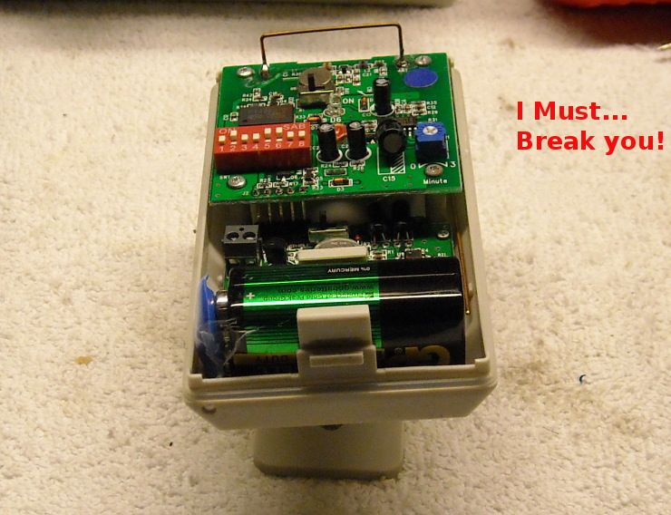
We'll deconstruct one of these PIRs, using the appropriate tools. 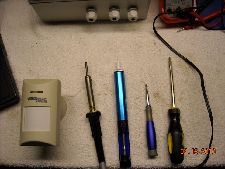
And the help of my favorite Brewer Patriot: 
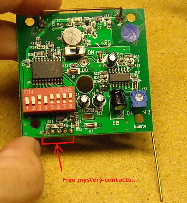
I started by removing the screws at the four corners of the transmitter board. A small screwdriver made short work of them. Attempting to pry off the board revealed that it was not only glued down at the top (via the antenna assembly), but also attached by five soldered connections at the lower left of the board: 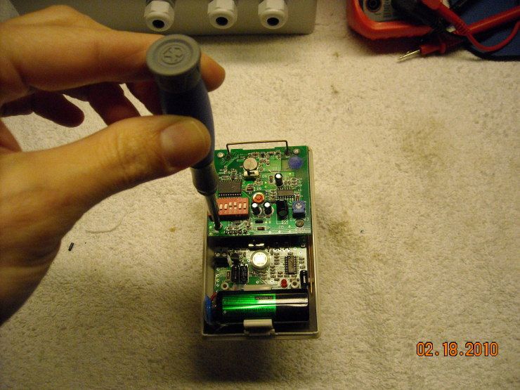
I attempted to desolder the connections, though that ended up being fruitless. I couldn't get enough heat to conduct through those connections to melt the solder without cooking the PCB (the desoldering tool you see there is one of the vacuum jobbies... sucks the solder right up once it's hot enough) 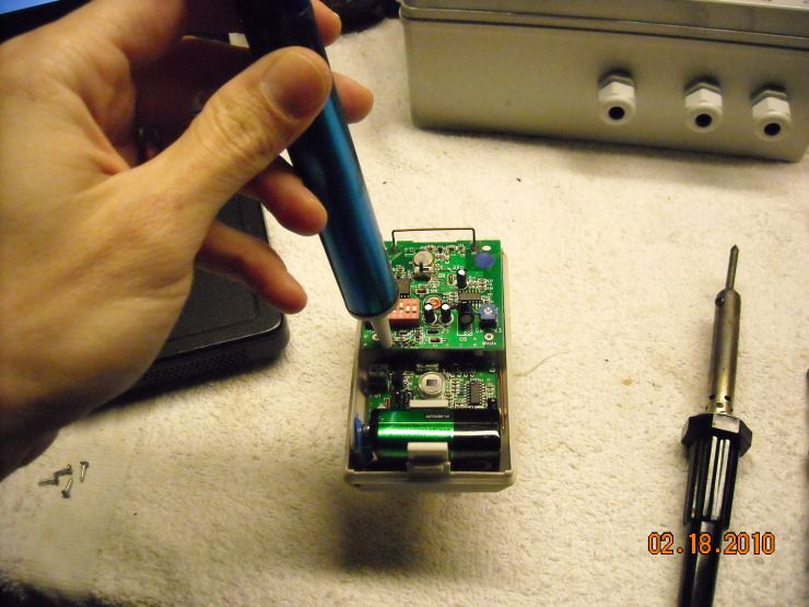
When this failed, I elected to remove both boards from the casing. The pyroelectric board has three screws, and requires an even smaller screwdriver than the top board (all are philips-head screws). It came up easily once the screws were removed: 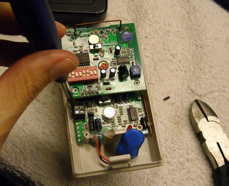
I then simply took a set of wire cutters and separated the two boards by cutting the five connection. Here is the back of the transmitter board, with the antenna annotated: 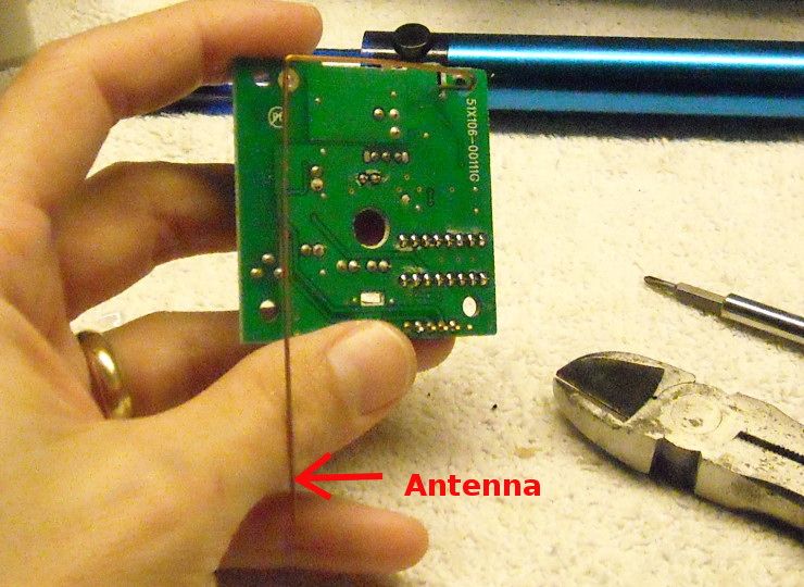
And here's the front: 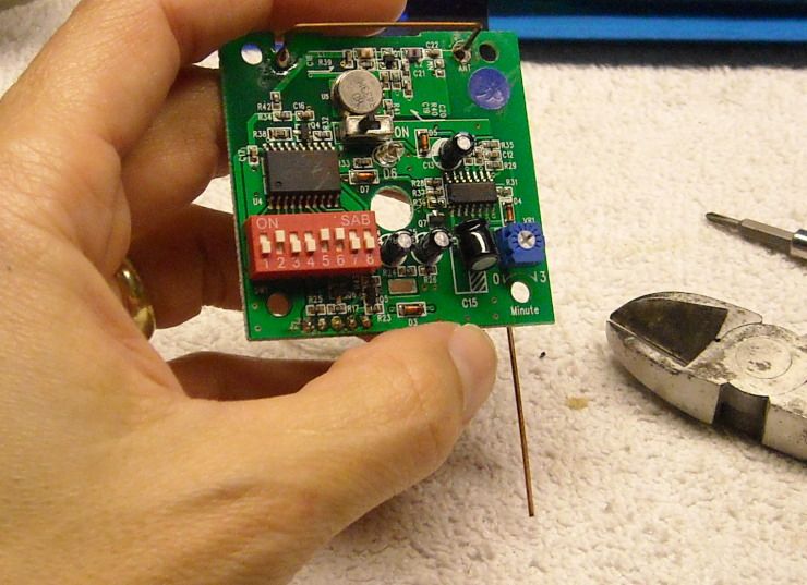
Now comes a moment of embarrassment. As I was looking at the separated PIR board, I noticed a small set of screw-down terminals. They didn't seem to serve any visible purpose, so I actually went and RTFM. Turns out, everything I just did was completely unnecessary. Those gray screw-down terminals can be used to connect another sensor element... so you could actually put a vibration sensor inside this casing, turn off the PIR, and actually have a vibration sensor just like the gray-boxed ones listed up-thread (though it would still look like a PIR). You could also run wires through the casing (hopefully you'd seal the hole) and attack a contact switch, magnetic reed switch, etc. Anyway, that's a perfectly good sensor ruined for nothing. Live and learn... and RTFM. 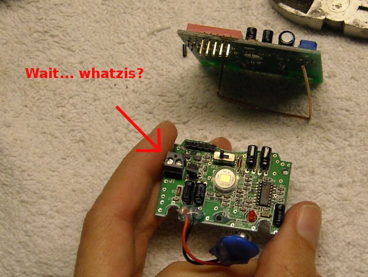
|
|
|
|
[#31]
Quoted:
In the spirit of Ivan Drago... http://i251.photobucket.com/albums/gg286/TGrayman/Voice%20Alert/Ivan5.jpg http://i251.photobucket.com/albums/gg286/TGrayman/Voice%20Alert/decon1.jpg We'll deconstruct one of these PIRs, using the appropriate tools. http://i251.photobucket.com/albums/gg286/TGrayman/Voice%20Alert/decontools.jpg And the help of my favorite Brewer Patriot: http://i251.photobucket.com/albums/gg286/TGrayman/Voice%20Alert/decon4.jpg I started by removing the screws at the four corners of the transmitter board. A small screwdriver made short work of them. Attempting to pry off the board revealed that it was not only glued down at the top (via the antenna assembly), but also attached by five soldered connections at the lower left of the board: http://i251.photobucket.com/albums/gg286/TGrayman/Voice%20Alert/decon2.jpg I attempted to desolder the connections, though that ended up being fruitless. I couldn't get enough heat to conduct through those connections to melt the solder without cooking the PCB (the desoldering tool you see there is one of the vacuum jobbies... sucks the solder right up once it's hot enough) http://i251.photobucket.com/albums/gg286/TGrayman/Voice%20Alert/desolder.jpg When this failed, I elected to remove both boards from the casing. The pyroelectric board has three screws, and requires an even smaller screwdriver than the top board (all are philips-head screws). It came up easily once the screws were removed: http://i251.photobucket.com/albums/gg286/TGrayman/Voice%20Alert/decon5.jpg I then simply took a set of wire cutters and separated the two boards by cutting the five connection. Here is the back of the transmitter board, with the antenna annotated: http://i251.photobucket.com/albums/gg286/TGrayman/Voice%20Alert/decon7.jpg And here's the front: http://i251.photobucket.com/albums/gg286/TGrayman/Voice%20Alert/decon8.jpg Now comes a moment of embarrassment. As I was looking at the separated PIR board, I noticed a small set of screw-down terminals. They didn't seem to serve any visible purpose, so I actually went and RTFM. Turns out, everything I just did was completely unnecessary. Those gray screw-down terminals can be used to connect another sensor element... so you could actually put a vibration sensor inside this casing, turn off the PIR, and actually have a vibration sensor just like the gray-boxed ones listed up-thread (though it would still look like a PIR). You could also run wires through the casing (hopefully you'd seal the hole) and attack a contact switch, magnetic reed switch, etc. Anyway, that's a perfectly good sensor ruined for nothing. Live and learn... and RTFM. http://i251.photobucket.com/albums/gg286/TGrayman/Voice%20Alert/decon6.jpg Looks like a versatile board... |
|
|
|
[#32]
Just adding to this thread:
I thought it might be nice to try out the Voice Alert transmitters with some other sensors. They make vibration and PIR sensors... but what about other sensors? I picked up a couple of these: 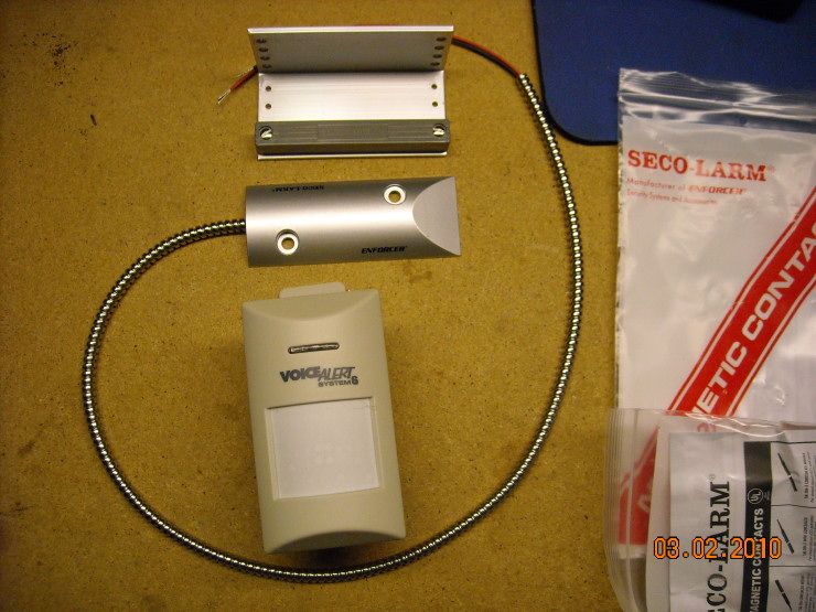
It's a gate/door/garage-door contact, made by Seco.. it's just about the most robust one they make, and since I'm planning on mounting it outdoors, I thought going heavy-duty early would maximize its duty cycle. This one has the option of being a NO (normally open) or NC (normally closed), depending on which wire you choose to connect. 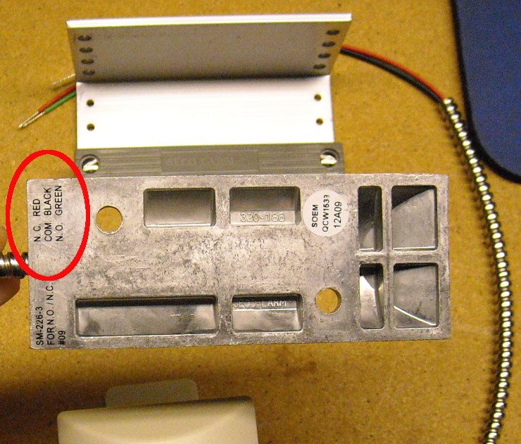
I have a couple of gates I'd like to alarm... we'll just see if this works. I'll update as I go along. |
|
|
|
[#33]
So anyway... here's a bit more of the skinny on that sensor.
It will be replacing this Voice Alert Vibration Sensor (note the moss/algae... it's been there for almost a year): 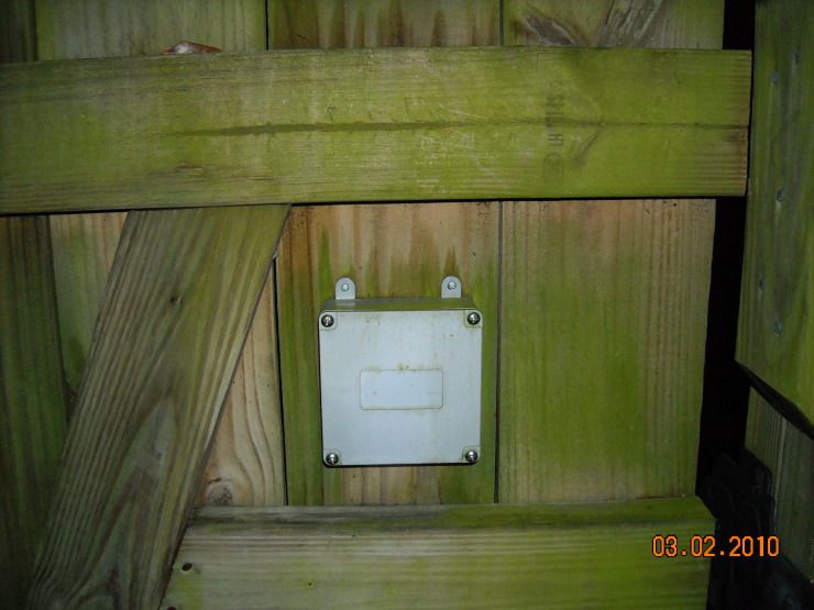
As you probably noted in the last post, this sensor has three wires compared to the usual alarm sensor, and can be set up as a "NO" (normally open), or NC (normally closed). A typical sensor has two wires, and I didn't know if the Voice Alert sensors would object to one type of sensor or another... so I bought a magnetic sensor that could be wired either way. As it happens, either way works: The black wire is the common ground, and the wires are polarity-independent... so it doesn't matter if the black wire goes in the right-hand or the left-hand hole on that J1 connector, provided it's paired with either its green (NO) or red (NC) counterpart. 
Here we have it wired up as NO (normally open): 
And here it is as you bring the magnet close to the reed switch. The LED in the center of that upper board is lit, showing that the sensor detected the change in condition of the alarm switch (from open to closed), and triggered the signal back to the base station. 
Here is the same thing happening in the NC position. Note we're using the red-and-black wires (it triggers as the magnet is removed from the sensor plate): 
What's interesting about this sensor is that it's really made for garage doors. It's pretty robust, and that sensor plate is designed to be screwed into a concrete floor. It also triggers a change in state at a considerable distance compared to a regular magnetic reed switch. This is a nice feature, since you may not get the same apposition of the magnet-and-sensor as you'd get on a conventional door. Garage doors have much more play in them, particularly considering insulation, door sills, and things that might require a magnetic switch to work at something greater than the usual almost-contact range. It works at about 2 and 1/4 inches: 
This should be just the thing for that gate. The greater distance at which this sensor operates also gives one the ability to hide it. That big vibration switch is pretty obvious (and also doesn't trigger if they open that gate veeeeeeerrrry slowwwwwly...), but you could even hide that magnetic switch under some trim wood, and it should still work. This thing has potential. Also, since you clearly can use those false-alarm-prone PIRs as simple transmitters, they're not a total loss. Every one of those Voice Alert systems ships with at least one of those PIRs... and rather than having to stuff it into a drawer because it drives you nuts with false alarms, you can press it into service as a slave transmitter for a considerably more useful sensor setup. |
|
|
|
[#34]
Very creative
|
|
|
|
[#35]
Quoted:
Very creative Thanks. That garage-door sensor was about 20 bucks... a bargain, particularly since it actually makes a working sensor out of that error-prone PIR. I'm embarrassed to say that I bought a bunch of those PIRs before I knew how touchy they were |
|
|
|
[#36]
Suggest you consider wiring the alarm out contacts of two PIR detectors in parallel and loosely colocate them, to dramatically reduce nuisance alarms.
|
|
|
|
[#37]
Quoted:
Suggest you consider wiring the alarm out contacts of two PIR detectors in parallel and loosely colocate them, to dramatically reduce nuisance alarms. Might want to wire them in series, parallel will just give you twice as many false alarms (not the desired effect |
|
|
|
[#38]
Quoted:
Suggest you consider wiring the alarm out contacts of two PIR detectors in parallel and loosely colocate them, to dramatically reduce nuisance alarms. That's a thought... unfortunately, if they're susceptible to the same falsing conditions, you'd have the same problem. |
|
|
|
[#39]
Further construction:
The PIRs have a tiny vent hole in the bottom of the casing, but it's not nearly large enough to pass the steel-sheathed sensor cable. Time to drill: 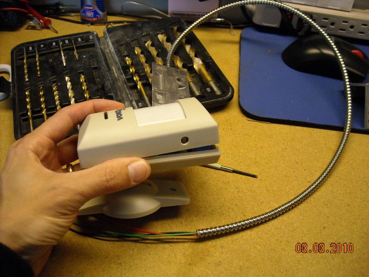
It took a 1/4" bit and a wee bit of enlarging beyond that for the cable to fit: 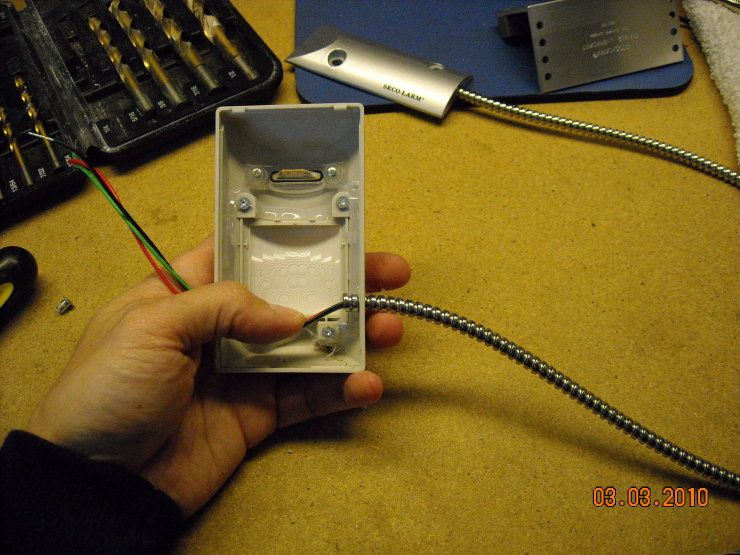
Hooked it up (I ended up cutting a bit off the end of each of those wires, just to they wouldn't inadvertently make contact with anything else on the circuit board): 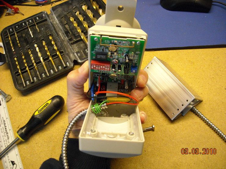
Removed the old vibration sensor. You can tell it had been there for a while (battery was still good... the battery life is exceptional in these sensors if they're not triggered often): 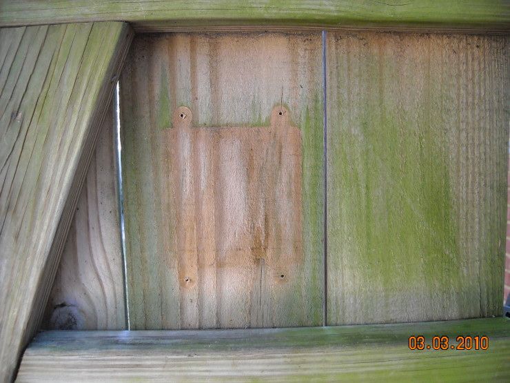
I initially considered mounting on the latch side... but there was no good way to do it, and make it invisible to anyone opening that gate. It also would have stuck out a bit, and I didn't need one of my kids opening up the side of their head on that metal bracket, so it went on the hinge side. Fortunately, the multiple mounting holes in that bracket allowed me to adjust the sensing distance just perfectly: 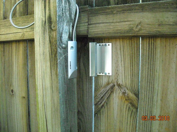
A couple of screws, and everything is mounted and ready. It alarms just as the gate is opening enough for a person to squeeze through. I sealed the area around that metal cabling with some silicone for water resistance. 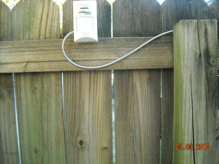
The view from the other side confirms that the sensor is invisible to anyone approaching the gate... surprise, surprise! 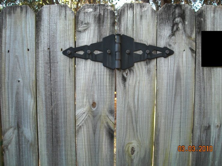
I opened up the old vibration sensor... it's still watertight after a year in the elements, and even the battery was still good. Excellent construction. 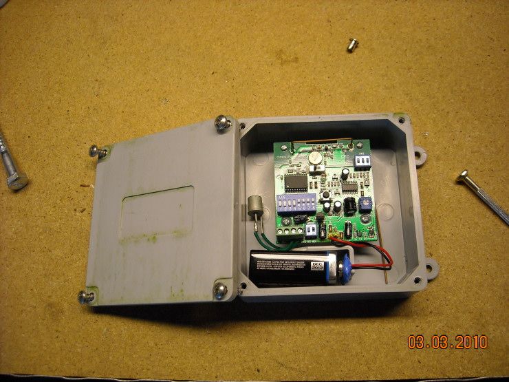
|
|
|
|
[#40]
That is awesome. WIsh I weren't so stoopid.
I know a fella that has simple motion detectors on the corners of his house and they are wired back to a panel with different color bulbs. Simple but smart. he can see which sensor is tripped, but only when in that room. I dont know if he has a different receiver for when he is mobile. He did not tell me that. Opsec i guess nct |
|
|
|
[#41]
Quoted:
That is awesome. WIsh I weren't so stoopid. I know a fella that has simple motion detectors on the corners of his house and they are wired back to a panel with different color bulbs. Simple but smart. he can see which sensor is tripped, but only when in that room. I dont know if he has a different receiver for when he is mobile. He did not tell me that. Opsec i guess nct This stuff isn't hard to do. Everything you need is in this thread... seriously., |
|
|
|
[#42]
For what its worth you can flip the magnet to the other side of the bracket to close the distance between the contact and the magnet. Might help if you need to fine tune it a bit more. Looks great !
|
|
|
|
[#43]
So I decided to play with that transmitter board a bit more. I wondered what the respective contacts from the PIR-to-transmitter board do:
I traced the leads from the battery using a known, good-and-working PIR: 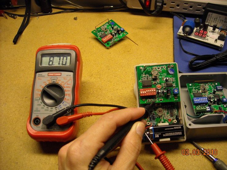
And found that the contacts on either end supply power to the transmitter board: 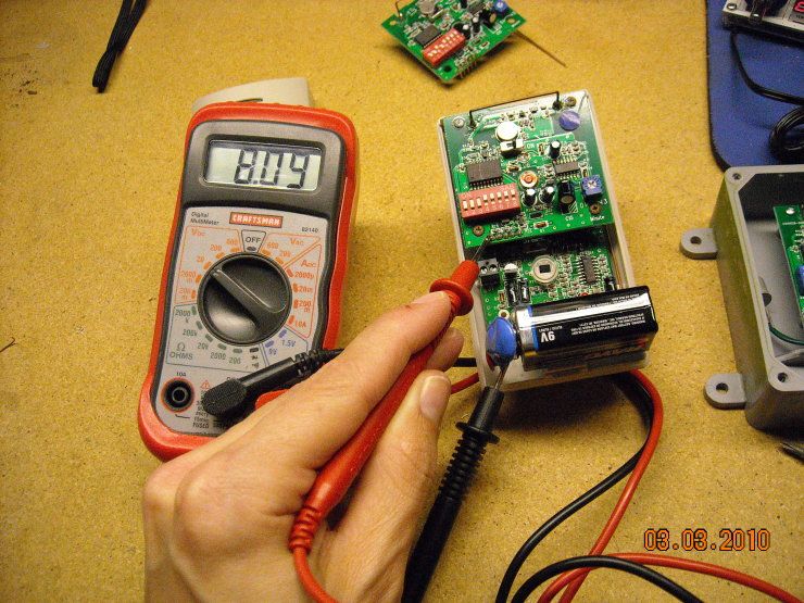
Applying 9VDC to contacts 1 and 5 (counting from the left) allowed me to test the board. Unfortunately, I ended up letting out the magic blue smoke before I finished... but discovered that shorting contacts 1 and 2 turned on the red LED. Shorting contacts 3 and 4 activated the transmitter, and triggered the appropriate message on the base station... so hooking up power to contacts 1 and 5, and hooking up a NO switch (Normally Open) to contacts 3 and 4 would allow you to use that transmitter board to connect a generic contact to your Voice Alert base. This particular one won't be of any use anymore... since it's dead... but it's all in the name of science. 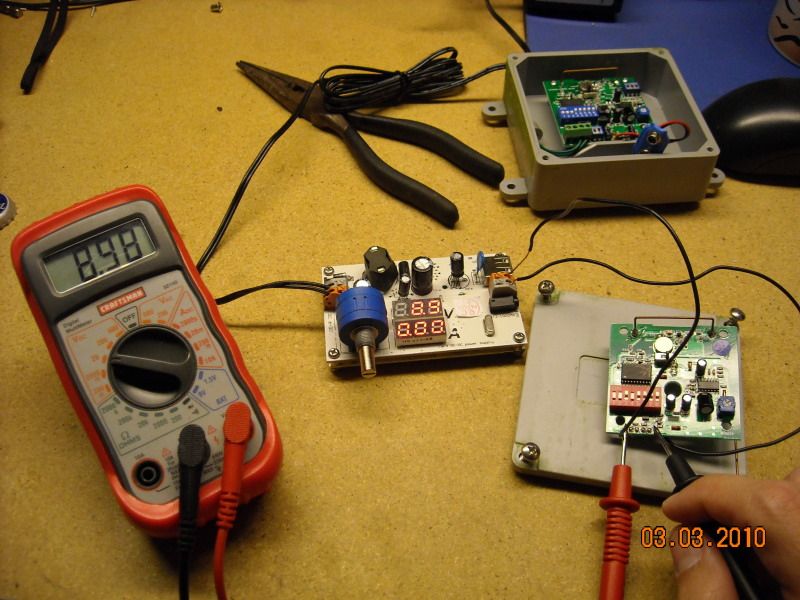
|
|
|
|
[#44]
So what about the base station?
The base station has six channels, assigned 1-6 on the front panel. Recording your own message is as simple as switching the main, three-position switch to "record" and holding down the respective button while you talk. It's a "Voice Alert 6," so you get six seconds of recording per channel. 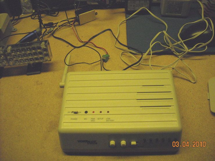
We're going to test some of the relays that this base station includes. Removing a small panel on the lower rear of the base reveals a set of connection. There are connections for each of the first four channels (the latter two don't have an associated relay), and an audio-out connection, so you can feed the audio from this base station into your home intercom, or a speaker system... saves having to have a base station in every room in the house. I have made a connection to the "open" connections on channel one... meaning that when channel one is triggered, the relay will close that connection (and open the connection on the other side of the common ground... not unlike a NO/NC setup). 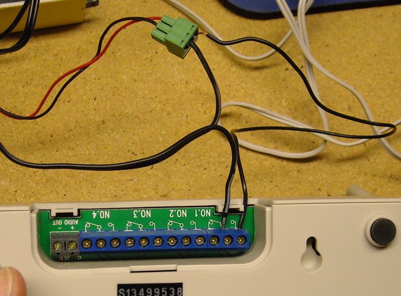
We'll test it with a PIR: 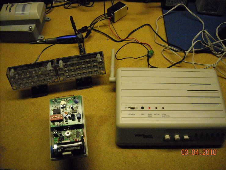
Those C-relays can take up to 24VDC, or 120VAC and 1AMP. We'll be using this strobe I bought a long time ago on Ebay: 
Get ready... 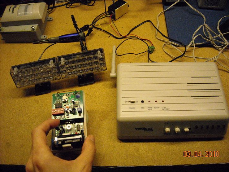
And triggering the PIR causes the strobe to flash for as long as the message is playing (six seconds). This, however, is configurable... and that relay can be programmed to stay on for 10 seconds, 30 seconds, 60 seconds... whatever: 
This could be handy if you're a visual guy... or just don't want an audible alarm. Just hook up a strobe or light, and turn down the volume. |
|
|
|
[#45]
|
|
|
|
[#46]
Those like Deal Extreme LEDs!!
|
|
|
|
[#47]
Quoted:
Those like Deal Extreme LEDs!! I honestly don't remember where I got those things. They run on 12V, but I've also run them off 9V (though they are a bit dimmer at 9V)... so the possibility exists that I might be able to run them off the same power supply that runs the base station. I have a plan in mind for those... and I have some more parts inbound. I'll post pics when I have it all together. |
|
|
|
[#48]
I have what appears to be the same system, although labeled Sound Alert by RAB. (RAB Lighting/rabweb.com) I found it when trying to find a decent sensor light for outdoors. (Heath/Zenith really suck IMO.) I've had great luck with this system and the sensor light I bought to try. (stealth 200 sensor/light, full assembly) This version appears to be cheaper, but RAB only seems to offer the basic sensors as upgrades. (no driveway tube, vibration, etc.) Of course they tout the X-10 compatibility but I thought that was just for the wire inputs.
This Sound Alert version comes with the base unit and two sensors. I bought one extra sensor when purchased. I did have false alarms from a sensor outside without significant shade from the sun. (also wasn't facing the sun) I suspect an outdoor/weatherproof box with clear door would fix this but haven't yet tried it. (Another shaded outdoor sensor rarely falses, and it's due to bushes moving in the wind. I could fix this with the covers but it's so rare I'd rather not lose the coverage.) I made the sun blasted one an interior sensor. Currently, it's set with a rapid cycle so it will basically signal continuously when it senses movement. That coupled with that nasty stock alert sound makes a nice supplement to the alarm systems already in place. Overall I've really liked the design/quality as well. I tightened a few of the sensor mounts and was surprised how accurate the plastic was molded, they almost seem seamless until you take them apart. I can't remember the last time I saw plastic made so cleanly. I did notice some water had apparently came up through the weep hole in one of the outside units. Didn't appear to cause a problem yet, but surely could. Anyway, I'm skeered of ebay but I'm definitely going to be on the lookout for a cheaper wireless vibration sensor! Thanks for the 411! |
|
|
|
[#49]
I have another base station inbound... and it's going to be the subject of experimentation.
We'll just see what can be done with this gadget. |
|
|
|
[#50]
The newest victim has arrived...

|
|
|
 Win a FREE Membership!
Sign up for the ARFCOM weekly newsletter and be entered to win a free ARFCOM membership. One new winner* is announced every week!
You will receive an email every Friday morning featuring the latest chatter from the hottest topics, breaking news surrounding legislation, as well as exclusive deals only available to ARFCOM email subscribers.

AR15.COM is the world's largest firearm community and is a gathering place for firearm enthusiasts of all types.
From hunters and military members, to competition shooters and general firearm enthusiasts, we welcome anyone who values and respects the way of the firearm.

Subscribe to our monthly Newsletter to receive firearm news, product discounts from your favorite Industry Partners, and more.
Copyright © 1996-2024 AR15.COM LLC. All Rights Reserved.
Any use of this content without express written consent is prohibited.
AR15.Com reserves the right to overwrite or replace any affiliate, commercial, or monetizable links, posted by users, with our own.