


Armory Sponsor


|
You mentioned a 20 LB L-P clyinder, you can get a hose adaptor kit at a good
hardware store or camper outlet. Needs to go from male PLO to male Colman, but be careful as local ordenance may require anything over XX lbs be keep out side of a biiuding because of expolsive possibilities. Check your local codes. sdshooter....................... |

|
Originally Posted By sdshootermsd:
You mentioned a 20 LB L-P clyinder, you can get a hose adaptor kit at a good hardware store or camper outlet. Needs to go from male PLO to male Colman, but be careful as local ordenance may require anything over XX lbs be keep out side of a biiuding because of expolsive possibilities. Check your local codes. sdshooter....................... thanks. well i already have the 20lb cylinder on my gas grill and i keep it in the garage. and that is where i am annealing. wanted to keep the flames out of my reloading room with all the powder 
i have the two fittings to put on the torch ends. now i just have to come up with 2 shorter flexible lines i can put in a tee and to the torches. then run the adapter hose from tank to Tee. |


|
Originally Posted By stevos758:
Did you just use a standard hole saw to cut the case turning plate? My DC motor showed up yesterday and I think my power supply showed up today!!! I cant wait to get this thing running. yes i did i will get you the sizes when i get home but i used one size to cut the hole in the plate and the next size bigger to make the plate that goes on the motor. then i sanded it a bit to make it fit just right. |
|
Originally Posted By BIGGDAWG:
Originally Posted By stevos758:
Did you just use a standard hole saw to cut the case turning plate? My DC motor showed up yesterday and I think my power supply showed up today!!! I cant wait to get this thing running. yes i did i will get you the sizes when i get home but i used one size to cut the hole in the plate and the next size bigger to make the plate that goes on the motor. then i sanded it a bit to make it fit just right. Ok. Thanks! |
|
Originally Posted By stevos758:
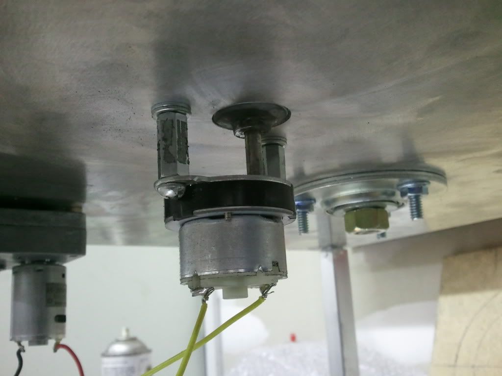
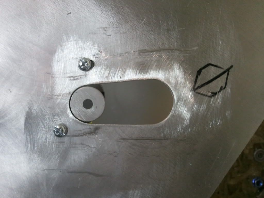
Did you just use a standard hole saw to cut the case turning plate? My DC motor showed up yesterday and I think my power supply showed up today!!! I cant wait to get this thing running. i used a 7/8 hole saw to cut the hole in the plate and 1 1/8 to cut the disc that goes on the motor. i then bought a collar with a set screw and had to drill out the hole slightly to fit the motor, then i used jb weld to attach the collar to the disc filling the hole in the disc with jb weld 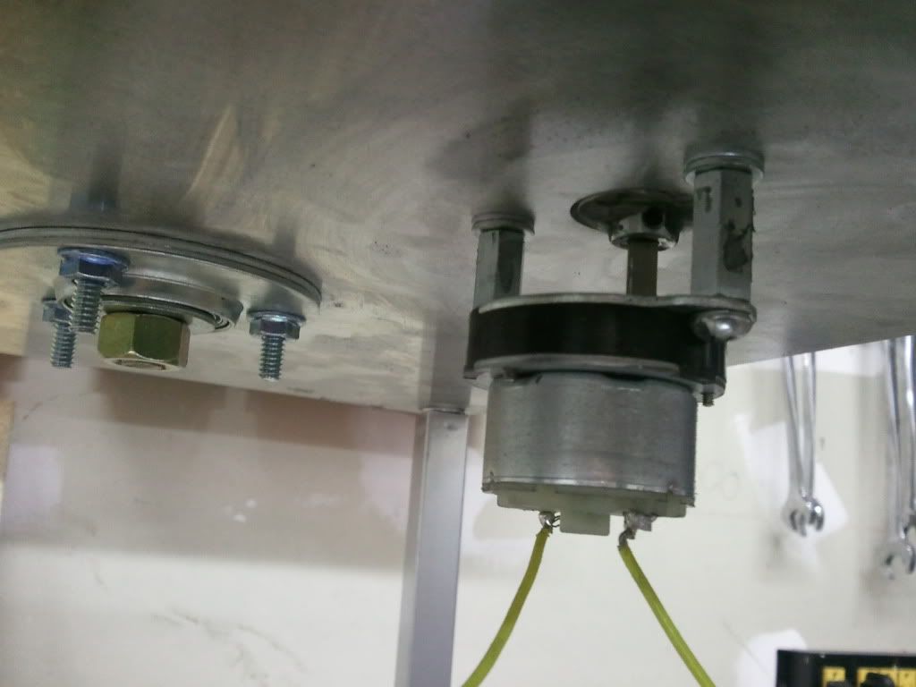
|
|
I also wanted to show you the parts i ordered from hornady to use on the annealer.
on the arm where the cases drop down to i needed a bushing like on the actual feeder on the press. so i ordered 1 each of the drop tubes and cut them to length and they fit perfectly into the 3/4 conduit. part 22 - large drop tube 398305 part 53 - small drop tube 398306 
this is where the tube goes. in this pic which is an old one i was trying to use one of the small bushings that came with the kit and they were too small. 
|
|
Originally Posted By stevos758:
Do you seem to have enough adjustment in the case rotating plate for 308? Do you even have to adjust it when switching to 308? yes i have enuff adjustment and yes i have to adjust for each case head change especially with spinning them faster like i am now. it really doesn't take much you just have to have the center of the case on the center of the motor that is why there has to be tension on the plate so it don't move till you want it to. |
|
Originally Posted By stevos758:
What is the easiest way to determine where the center of the case is before cutting the hole? i had everything set up and ran the advance motor. then when it was stopped (here is where the tension comes in) i took the smallest case head i was going to use –– 223, colored the base with a sharpie with out the primer in it, put it in the notch of the plate and twisted it marking the plate. when you remove the case there is a void where the primer isn't that is where i drilled. it is also helpful to put a sharpie in the notch and rotate the plate for a ways marking the center of the hole for when you cut the notch |
|
Originally Posted By stevos758:
What is the easiest way to determine where the center of the case is before cutting the hole? i forgot to say you have to determine what hole you are going to use to anneal in and that centers it best with your torch set up. amd mark that one that is where you do the sharpie on the case head. |


|
Originally Posted By stevos758:
What are you using for the fastening hardware for the case turning motor. I need to order some standoffs. I am almost done with the annealer minus the case feeder part. they are 10-24 thread turn buckles i had to drill the holes out on the motor so 10-24 bolts would fit. then i shimmed as needed. i found mine at my farm and fleet by the threaded rod and steel. |

|
Originally Posted By stevos758:
http://images54.fotki.com/v289/photos/5/2177835/11178721/2012111318_54_42-vi.jpg Here it is so far. Getting there. looking good |
|
IMHO, a much better way to control the cycle speed isn't by varying the voltage. That's hard on a motor and take an expensive power supply. The only way I would recommend doing that is with a PWM power supply.
The way I did it with my annealer was to use a wind-shield wiper motor. Free from a junk yard. On the intermittent setting the motor cycles 1 revolution then stops and delays. This delay time is actually controlled by several fixed value resistors that correlate to the settings on your wiper control switch. If you remove the motor from the car you have to add the resistors back into the system to get the proper delay. Best way to add a resistor in if you want continously variable timing is to use a potentiometer. Adding a pot allows you variable delay; you may have to add fixed resistors in series or parallel to get the desired adjustment range however. Mine is currently set up to give anywhere from 1-18 second delay time right now. Best of all is that you just use a fixed 12 VDC power supply; I used an old PC power supply that I converted to a 3/5.5/12 VDC power supply for about $4. Total cost in my entire annealer project was $4 for power supply, $5 for the pot, $10 in some metal that I didn't already have in the scrap pile, and $40 for the 2 torches. The motor was free and it's already designed to do exactly what everybody is trying to "rig" these other DC motors to do. The only problem I had was because the motor runs at a fixed rpm that is faster than most motors are driven on annealers sometimes the drive arm would impact the disc abruptly knocking brass over. I switched the drive mechanism to a drive-rod/crank style and it's perfect. The disc has a "soft-start" and "soft-stop" feature as a result. There is a 2nd arm attached the arm of the crank on the motor. The 2nd arm pushes against the notches on the plate as the crank pushes forward and reset back to the next notch as the crank returns to its home position. |

|
Interesting, thanks for sharing...may have to give it a try. Originally Posted By SigOwner_P229: IMHO, a much better way to control the cycle speed isn't by varying the voltage. That's hard on a motor and take an expensive power supply. The only way I would recommend doing that is with a PWM power supply. The way I did it with my annealer was to use a wind-shield wiper motor. Free from a junk yard. On the intermittent setting the motor cycles 1 revolution then stops and delays. This delay time is actually controlled by several fixed value resistors that correlate to the settings on your wiper control switch. If you remove the motor from the car you have to add the resistors back into the system to get the proper delay. Best way to add a resistor in if you want continously variable timing is to use a potentiometer. Adding a pot allows you variable delay; you may have to add fixed resistors in series or parallel to get the desired adjustment range however. Mine is currently set up to give anywhere from 1-18 second delay time right now. Best of all is that you just use a fixed 12 VDC power supply; I used an old PC power supply that I converted to a 3/5.5/12 VDC power supply for about $4. Total cost in my entire annealer project was $4 for power supply, $5 for the pot, $10 in some metal that I didn't already have in the scrap pile, and $40 for the 2 torches. The motor was free and it's already designed to do exactly what everybody is trying to "rig" these other DC motors to do. The only problem I had was because the motor runs at a fixed rpm that is faster than most motors are driven on annealers sometimes the drive arm would impact the disc abruptly knocking brass over. I switched the drive mechanism to a drive-rod/crank style and it's perfect. The disc has a "soft-start" and "soft-stop" feature as a result. There is a 2nd arm attached the arm of the crank on the motor. The 2nd arm pushes against the notches on the plate as the crank pushes forward and reset back to the next notch as the crank returns to its home position. |

|
I made some progress on mine. I don't have any welding tools or skills, so wood it is. The decks are 1/2" oak plywood and they sit in dado's inside the 1" x 1 1/2" oak frame. The aluminum skid plate under the blade is a mason's hawk with the handle and insert removed. The bearing set up is the same as BIGGDAWG's. To get around welding nuts to the torch holders for the thumb screws I drilled and tapped 10-24 holes.
I still have to final sand and apply a tung oil finish. In the last photos the decks were tung oiled before I put the frames on. The main motor, case spinning motor and power supply are enroute. I'm having a problem with balancing the blade, so I'm looking for a solution. I think the plastic layer BIGGDAWG used should fix that problem. Since I didn't have a snowmobile skid plate here in Florida I used two layers of lexan, 13/64" total, and it resolved the issue perfectly. Once I get it running (not doing the case feeder) I'll post the end result. Thanks for the help BIGGDAWG!   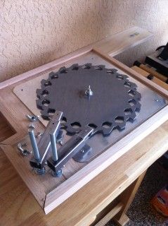
  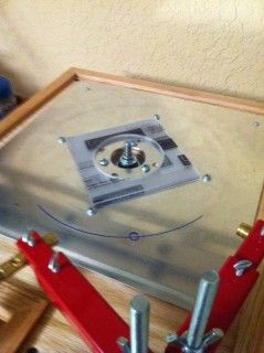

ETA: picture and lexan fix |
|
Originally Posted By RLR350:
I made some progress on mine. I don't have any welding tools or skills, so wood it is. The decks are 1/2" oak plywood and they sit in dado's inside the 1" x 1 1/2" oak frame. The aluminum skid plate under the blade is a mason's hawk with the handle and insert removed. The bearing set up is the same as BIGDAWG's. To get around welding nuts to the torch holders for the thumb screws I drilled and tapped 10-24 holes. I still have to final sand and apply a tung oil finish. In the last photos the decks were tung oiled before I put the frames on. The main motor, case spinning motor and power supply are enroute. I'm having a problem with balancing the blade, so I'm looking for a solution. I think the plastic layer BIGDAWG used should fix that problem. Once I get it running (not doing the case feeder) I'll post the end result. Thanks for the help BIGDAWG! http://i369.photobucket.com/albums/oo134/rlr350/annealer3_zpsa12c1a4b.jpg http://i369.photobucket.com/albums/oo134/rlr350/annealer1_zpsf2953784.jpg http://i369.photobucket.com/albums/oo134/rlr350/annealer4_zps8e36789e.jpg http://i369.photobucket.com/albums/oo134/rlr350/annealer2_zps1223a23d.jpg http://i369.photobucket.com/albums/oo134/rlr350/annealer5_zps4cb349b3.jpg that looks great!!!! love the use of wood that will make this work for many more people that don't have a welder. thanks for posting the progress pics. |
|
Originally Posted By RLR350:
I made some progress on mine. I don't have any welding tools or skills, so wood it is. The decks are 1/2" oak plywood and they sit in dado's inside the 1" x 1 1/2" oak frame. The aluminum skid plate under the blade is a mason's hawk with the handle and insert removed. The bearing set up is the same as BIGGDAWG's. To get around welding nuts to the torch holders for the thumb screws I drilled and tapped 10-24 holes. I still have to final sand and apply a tung oil finish. In the last photos the decks were tung oiled before I put the frames on. The main motor, case spinning motor and power supply are enroute. I'm having a problem with balancing the blade, so I'm looking for a solution. I think the plastic layer BIGGDAWG used should fix that problem. Once I get it running (not doing the case feeder) I'll post the end result. Thanks for the help BIGGDAWG! http://i369.photobucket.com/albums/oo134/rlr350/annealer3_zpsa12c1a4b.jpg http://i369.photobucket.com/albums/oo134/rlr350/annealer1_zpsf2953784.jpg http://i369.photobucket.com/albums/oo134/rlr350/annealer4_zps8e36789e.jpg http://i369.photobucket.com/albums/oo134/rlr350/annealer2_zps1223a23d.jpg http://i369.photobucket.com/albums/oo134/rlr350/annealer5_zps4cb349b3.jpg Yes! Very nice. I am still waiting to go to the hardware store to pick up my standoffs for the case turner. |

Global Warming Hoax Skeptic before it was cool
Joined:
Jun 2007
Posts:
21151
EE: 100% (1)
 WA, USA
|
The two motors and power supply arrived. I'm waiting on a few switches and an arbor extension.
The thickness of the 1/2" plywood deck was too much for the 2L009 motor's arbor to extend through. I ordered this extension that should work out well. I'm going to lower the legs about an inch to fit the power supply better and put a switch panel to the left of the catch bin. BIGGDAWG - Would it be possible to get a picture of your wiring? I saw the two you posted, but am having a hard time following them. I'm interested in how you connected the two motors to the switches, including the potentiometer for the faster case turn motor. Like you mentioned, I noticed from a little playing that the lower rpm case turn motor slows a little too much when the voltage is turned down to slow the 2L009 motor's speed. I'll probably look at a faster motor for the case turning. Thanks. 
|
|
Originally Posted By RLR350:
The two motors and power supply arrived. I'm waiting on a few switches and an arbor extension. The thickness of the 1/2" plywood deck was too much for the 2L009 motor's arbor to extend through. I ordered this extension that should work out well. I'm going to lower the legs about an inch to fit the power supply better and put a switch panel to the left of the catch bin. BIGGDAWG - Would it be possible to get a picture of your wiring? I saw the two you posted, but am having a hard time following them. I'm interested in how you connected the two motors to the switches, including the potentiometer for the faster case turn motor. Like you mentioned, I noticed from a little playing that the lower rpm case turn motor slows a little too much when the voltage is turned down to slow the 2L009 motor's speed. I'll probably look at a faster motor for the case turning. Thanks. http://i369.photobucket.com/albums/oo134/rlr350/annealer8_zpsed7aa1a8.jpg here is a drawing of how i wired mine. if you go to the faster motor you will want to get a 50 or 100 ohm 2 watt potentiometer the 25 i had needed another 20 ohms with it to get to a decent speed. 
|

|
Originally Posted By RLR350:
Originally Posted By sburggsx:
I'm not even sure why I'd need it, but WOW that's cool!  I'm not sure why I need one either, but it's a fun project and thanks to this thread it was pretty easy. Thanks for the diagram BIGGDAWG. That makes sense now. your welcome glad i could help |


|
Originally Posted By dryflash3:
Great thread, I like the different materials being used.  Yeah, good job RLR350! I got my blade and my motor for mine, but I've only just got the cad drawings done, otherwise. I'm getting covered up at work which is a good thing......finally! And at home too....doing some remodeling....replaced all my '70's era aluminum windows with Milgards. Wow...made a big difference. This winter will be draft-free cozy. . Anyway, I'm glad to see somebody else is trying wood! With absolutely no intention of raining on a very talented metal worker's parade (BIGGDAWG, of course), I'm of the opinion that wood can work just as good as metal, and has the potential to be very attractive in its own right, as RLR350's new rig demonstrates! Just wish I had more time right now....too many irons in the fire, and the holidays snuck up on me too.
Dryflash, I figured you'd have your wood one built first.....he beat us both.
|
Global Warming Hoax Skeptic before it was cool
Joined:
Jun 2007
Posts:
21191
EE: 100% (1)
WA, USA
|
Still on the fence, don't know if I will build one. If I did build one, it would be out of metal. I'm not a real welder, but I can stick two pieces of metal together.
 |
Selling agent for Algores carbon credit scam.
Shooting and Reloading, one hobby feeds the other.
Shooting and Reloading, one hobby feeds the other.
|
Finished. Here is a video of the test run. The brass has been used several times for testing and will be tossed.
I came up with a different design for the actuator using a threaded rod connector and a set screw. This got past the problem associated with the thickness of the wood compared to the thickness of the metal framed ones. I also used a smaller threaded rod connector under the case spinning plate. I have the arbor extension from Zoro Tools enroute and will probably switch to it just to lower the actuator a little. The case spinner was difficult to align. I added a small piece of plastic (cut credit card) to keep the cases from spinning away from the flame. It adds a slight kick to the brass when it leaves the flame, but works well. I plan to change the motor to a faster one as BIGGDAWG mentioned, but it hasn't arrived yet. The credit card should help as I can imagine the faster motor will try to spin the cases off even more. The plastic piece sits on a washer and is mounted to the deck under the blade with a screw. The last picture is some once fired, tumbled LC brass I ran through. The uneven color below the neck is the result of not spinning faster enough (less than a full turn at the speed I was using). With a little practice using Tempilac and a faster case spinning motor it should work well. Thanks again to jmorris and BIGGDAWG.  
 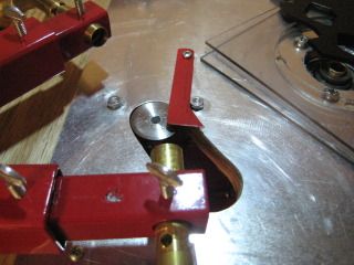
 
 
|
|
That turned out great. i like the credit card set up. that gave me an idea i am going to try. -- piece of spring wire to hold the case back in the v for those times you can't get it adjusted just right. and yes centering the spin motor on the case is more important with the faster motor. great work and thanks for sharing. Originally Posted By RLR350:
Finished. Here is a video of the test run. The brass has been used several times for testing and will be tossed. I came up with a different design for the actuator using a threaded rod connector and a set screw. This got past the problem associated with the thickness of the wood compared to the thickness of the metal framed ones. I also used a smaller threaded rod connector under the case spinning plate. I have the arbor extension from Zoro Tools enroute and will probably switch to it just to lower the actuator a little. The case spinner was difficult to align. I added a small piece of plastic (cut credit card) to keep the cases from spinning away from the flame. It adds a slight kick to the brass when it leaves the flame, but works well. I plan to change the motor to a faster one as BIGGDAWG mentioned, but it hasn't arrived yet. The credit card should help as I can imagine the faster motor will try to spin the cases off even more. The plastic piece sits on a washer and is mounted under the blase with a screw. The last picture is some once fired, tumbled LC brass I ran through. The uneven color below the neck is the result of not spinning faster enough (less than a full turn at the speed I using). With a little practice using Tempilac and a faster case spinning motor it should work well. Thanks again to jmorris and BIGGDAWG.  http://www.youtube.com/watch?v=kJUIYCjclXo http://i369.photobucket.com/albums/oo134/rlr350/IMG_0722_zpseb5b6c47.jpg http://www.youtube.com/watch?v=kJUIYCjclXo http://i369.photobucket.com/albums/oo134/rlr350/IMG_0722_zpseb5b6c47.jpg
http://i369.photobucket.com/albums/oo134/rlr350/IMG_0710_zps158f1eba.jpg http://i369.photobucket.com/albums/oo134/rlr350/IMG_0711_zps30e972be.jpg http://i369.photobucket.com/albums/oo134/rlr350/IMG_0709_zps584357ad.jpg http://i369.photobucket.com/albums/oo134/rlr350/IMG_0718_zpse0a685f7.jpg http://i369.photobucket.com/albums/oo134/rlr350/IMG_0720_zpse11aa08f.jpg http://i369.photobucket.com/albums/oo134/rlr350/IMG_0723_zpsc5c4cd1a.jpg |
|
Thanks for reporting...great video. Nice little machine you made! I like the wood....I'd better...because welding is not an free option for me.
You guys really think the brass rotating motor is worth the trouble? The flames appear to dance all around the brass whether it turns or not. I'll probably try it without, but reserve the right to add one later.
I like the idea of using an alum. mason's hock, which gives me the idea of buying a plastic cutting board at a kitchen store made of self-lubricating VHPE plastic. |
|
I'm not sure if the rotating motor is worth the trouble, but in the end it was fun to tinker with (I think). I probably had more difficulty with it than BIGGDAWG did. It may be because of the thin layer of aluminum I was working with (combined with my lack of metal working skills - I hated metal shop in school, loved wood shop.)
If the spinner isn't used it may be a good idea to let the brass rest one space before it drops. My thinking is it would let the heat even out - if that even matters. The only other thing would be cosmetic; a faster spin would even out the heat marks. Some people might find that important. A cutting board would be interesting, although that stuff is tough to cut on a table saw. The heat from the blade melts and sticks to it. I liked your idea of a counter top sink cut out. The formica would work great. Heat shouldn't be a problem for either because it doesn't really travel past the torch arm. I can touch the blade and aluminum plate right after using the machine. After seeing some of your other projects I'm really looking forward to seeing what you come up with! |
|
Originally Posted By RLR350: Finished. Here is a video of the test run. The brass has been used several times for testing and will be tossed. I came up with a different design for the actuator using a threaded rod connector and a set screw. This got past the problem associated with the thickness of the wood compared to the thickness of the metal framed ones. I also used a smaller threaded rod connector under the case spinning plate. I have the arbor extension from Zoro Tools enroute and will probably switch to it just to lower the actuator a little. The case spinner was difficult to align. I added a small piece of plastic (cut credit card) to keep the cases from spinning away from the flame. It adds a slight kick to the brass when it leaves the flame, but works well. I plan to change the motor to a faster one as BIGGDAWG mentioned, but it hasn't arrived yet. The credit card should help as I can imagine the faster motor will try to spin the cases off even more. The plastic piece sits on a washer and is mounted to the deck under the blade with a screw. The last picture is some once fired, tumbled LC brass I ran through. The uneven color below the neck is the result of not spinning faster enough (less than a full turn at the speed I was using). With a little practice using Tempilac and a faster case spinning motor it should work well. Thanks again to jmorris and BIGGDAWG. http://www.youtube.com/watch?v=kJUIYCjclXo http://i369.photobucket.com/albums/oo134/rlr350/IMG_0722_zpseb5b6c47.jpghttp://i369.photobucket.com/albums/oo134/rlr350/IMG_0710_zps158f1eba.jpg http://i369.photobucket.com/albums/oo134/rlr350/IMG_0711_zps30e972be.jpg http://i369.photobucket.com/albums/oo134/rlr350/IMG_0709_zps584357ad.jpg http://i369.photobucket.com/albums/oo134/rlr350/IMG_0718_zpse0a685f7.jpg http://i369.photobucket.com/albums/oo134/rlr350/IMG_0720_zpse11aa08f.jpg http://i369.photobucket.com/albums/oo134/rlr350/IMG_0723_zpsc5c4cd1a.jpg Nice work, very impressive!
|

|
Originally Posted By stevos758:
http://images58.fotki.com/v612/photos/5/2177835/11178721/2012112619_21_15-vi.jpg Almost there. Need to machine a case turning plate. Mine wobbles and the cases don't rotate properly. Looks good yes getting the case spin right takes a little time but i think it is worth it. going to work on a mod after seeing RLR350's credit card mod. think i am going to try to come up with a small spring wire to hold the cases back. |
|
Originally Posted By stevos758:
Do you have a link for the 200rpm motor you installed for hte case feeder? I also would like to speed mine up. here is the link http://www.ebay.com/itm/320916490243?ssPageName=STRK:MEWNX:IT&_trksid=p3984.m1497.l2649 now this one is a bit too fast for me so you will want at least a 25 ohm variable resistor -- i used that with a 10 ohm resistor at first and it was ok but still a little fast. so i bought a 100 ohm 2 watt resistor and that works much better. don't need to go all the way to 100 i think 50 ohm would be perfect but i couldn't find one. like this one http://www.jameco.com/webapp/wcs/stores/servlet/ProductDisplay?langId=-1&storeId=10001&catalogId=10001&pa=241568&productId=241568&keyCode=WSF&CID=GOOG&gclid=CPrlw82I8rMCFexAMgodRU8AxA |
|
Originally Posted By stevos758:
Do you have a link for the 200rpm motor you installed for hte case feeder? I also would like to speed mine up. I couldn't find them in stock at the usual places. Here is one on ebay that has the same mounting as the original. 200 rpm identical to 30 rpm Here is one that looks promising, but you would have to redo the mount. 200 rpm geared motor I might try this to vary the speed on the 200 rpm similar to the original. Speed Regulator Since I have the original working I'm going to take more time with a new spinning plate and way to attach it when I get ready to install the faster one. Since you have access to a lathe, did you try machining a 1" diameter (or whatever your deck's hole size is) by ~3/4" long piece of aluminum with a hole down the middle the same size as the motor's arbor. I think attaching it to the motor with a set screw would be easier to align since the piece you start with is already perfectly round and flat. As you probably saw on yours, a slight wobble causes the brass to "trip" entering the plate sometimes when the edge of the spinning plate gets too high or low at the point the brass is sliding on. I found that that making sure the blade stops the brass dead center on the plate makes a big difference. I adjusted this by messing with the distance from center of the bolt on the blades actuating arm. (I made about four of them until I got it right - the other option would have been moving the big motor by drilling larger mounting holes so it could be adjusted.) Looks good so far - good luck. Looking forward to seeing what you come up with. |
Armory Sponsor