


Posted: 12/31/2013 2:26:15 PM EDT
|
I don't actually know how long each wire is, because they're been up for like two weeks, and I don't have a measuring tape long enough. I cut the wire about four years ago, saw how big it was, and realized it wasn't going to work, and put it away. I finally moved somewhere to put it up, so I did. Now I have issues.
I never really paid much attention to my OCFD until I systematically have been removing poor practices from my station. Currently, I have a 90ft-45ft OCFD in the air. It's out the third story window at almost exactly 8.23 meters (27ft) high on the addition, and as demonstrated in the paint diagram below, It's a 3rd story window, and it's attached to the corner of the house there. It's fed with a commercially made 4:1 balun and 50ft of RG8 with a small drip/strain loop (~4") that drops straight down to the ground, then lead along the ground to my comms room, on the ground floor, and through the window, outlined in green. The ends are tied off using insulators tied to rope wrapped around trees. It's currently very dry. 
(close to scale) The closest approximation of the angles is like so: 
(not to scale, but angles are close to scale) I currently get the following SWRs: 160m: 1.810: LOL 1.850: LOL 1.900: LOL 1.950: 21.1 80m: 3.530- 2.4 3.595- 2.2 3.810- 3.3 3.910 -3.9 3.995- 4.6 40m: 7.030- 5.3 7.120- 4.9 7.180- 4.9 7.250- 4.9 7.295- 4.6 30m: 10.150- 3.3 20m: 14.030- 1.7 14.145- 1.4 14.230- 1.0 14.300- 1.0 14.345- 1.0 17m: 18.080- 2.6 18.150- 2.6 15m: 21.030- 1.6 21.195- 1.4 21.280- 1.0 21.445- 1.0 12m: 24.900- 5.3 24.985- 5.9 10m: 28.100- 1.9 28.300- 1.7 28.600- 1.4 28.700- 1.0 29.000- 1.0 29.270- 1.0 29.350- 1.5 29.895- 2.0 Seems like it's resonant at 10m, 15m, and 20m, But why isn't it resonant at 40m? Yeah, I'm not trying to use 160m w/o a tuner... With a tuner (mfj 993b), I can tune everything to between 1.0 and 1.4, most of the time 1.0 if I work at it. I mean, it works, I've made quite a few contacts with it, but it's always about maximizing what you have. Questions Should I feed it with ladder line instead? Do I need a different balun? I'm not sure if I should trim the ends, or add more, which would be more beneficial? Should I just not care and keep on trucking because I have a tuner? Am I being too anal retentive? Should I just put up another antenna for 80 and 40 and be done with it? (If yes, where?) |
|
Quoted:
Do you have an antenna analyzer or are you making your measurments from the radio? Making measurements on the tuner (MFJ 993b): 
Well, after running some math with the help of a couple hams on the air on 75m, I figured out that I'm putting out 87W on the air at 75m. I'm considering ordering this one, the feedback on all his auctions all say "fast shipping" so whatever that means. lol. |
|
I have the Autek RF-1 analyzer. Works well.
http://www.autekresearch.com/index.htm |
|
Check you IM
JLE Quoted:Making measurements on the tuner (MFJ 993b):
I'm considering ordering this one, the feedback on all his auctions all say "fast shipping" so whatever that means. lol. |
|
Responses in bold.
Quoted:
Is your balun a voltage balun or current balun? Buxcomm 4:1 Current BALUN 1.6 to 60 Mhz SSB Rated at 1000 watts. Do you have a good station ground? Yes. 8ft ground round rod is 6ft into the ground, less than 10 feet electrically away from the station. Single point ground in the station. Is the antenna wire insulated or bare? Insulated 14ga THHN wire. This stuff here. |
|
Here is a good explaination of how OCF dipoles work.
Linky Maybe it will help you figure out what you need to do. |
|
The reason I asked about insulated or bare, for the same frequency, insulated will be shorter than bare.
You really need to get some good measurements of exactly how much wire you have on each leg. 80 m being a little high is not unusual. 40 meters being that high is. I would expect 40 m to be down about 2:1. The balun is a good one for OCFDs. I have two of those myself. |
|
Quoted:
Readings lead me to believe the wire is too short. These... 80m: 3.530- 2.4 3.595- 2.2 3.810- 3.3 3.910 -3.9 3.995- 4.6 20m: 14.030- 1.7 14.145- 1.4 14.230- 1.0 14.300- 1.0 14.345- 1.0 Indicate to me that the overall length is about right. Well, maybe a little short. However this: 40m: 7.030- 5.3 7.120- 4.9 7.180- 4.9 7.250- 4.9 7.295- 4.6 Should be lower SWR. 30m: 10.150- 3.3 and 15m: 21.030- 1.6 21.195- 1.4 21.280- 1.0 21.445- 1.0 And these two bands should be much higher SWR for a 1/3-2/3 OCFD, and not tunable. This all indicates to me that the split is not correct, or not optimum, and is certainly not 1/3-2/3. And this band: 17m: 18.080- 2.6 18.150- 2.6 Is usually lower SWR for an 80 meter 1/3-2/3 OCFD. I would expect to see 1.2 to 1.5 SWR for this whole band for a 1/3-2/3 OCFD. And this band: 10m: 28.100- 1.9 28.300- 1.7 28.600- 1.4 28.700- 1.0 29.000- 1.0 29.270- 1.0 29.350- 1.5 29.895- 2.0 Is usually a little higher, 2:1 to 3:1, for the same 1/3-2/3 OCFD. Tunable but usually higher. |
|
K. I'll go buy a tape measure that's longer than 10m tomorrow and measure it. I suspect you guys are right and it's a little short. I'm half tempted to just let it hang there for a while and stretch, but I'm not sure how much I'd get out of it.
Tomorrow I'll do the following to see if I get any different readings: make a "coaxial balun" where the coax touches the ground by wrapping it 10 or so times clip some test-leads to it tomorrow and change the length +1ft on one end at a time buy a longer tape measure and actually measure it out I suspect #3 will be the biggest change, but being the cheapskate I am, I have to try the "free" options first. Soldering more wire to the ends is easy and "free" as is making a "coax balun" at the ground level. |
|
I do my measuring with a 25' tape. Get my wife... here, Honey, hold this... then when I get to 25' of wire, get her to hold it there and measure the next section.
Then she says to me, "Why not put a nail in the wood fence, tie off one end there, then make some little marks every 10' or 20' or whatever you want? Then you can do this by yourself." Sheesh! Women!!! They think they're so smart! |
|
Harbor Freight Tape measure 165' is my friend! Linky
It certainly helps to have tape measure long engough to measure the wire in one shot. |
|
Happy new year everyone.
I put 9 of these right at the point where the coax touches the ground. 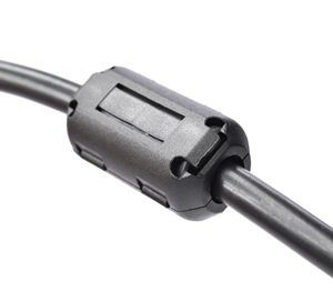
What do you know, it made an improvement, and here are my new numbers (in green): 80m: 3.530- 2.4 2.1 3.595- 2.2 2.0 3.810- 3.3 2.8 3.910 -3.9 3.5 3.995- 4.6 3.8 40m: 7.030- 5.3 4.6 7.120- 4.9 4.0 7.180- 4.9 4.0 7.250- 4.9 4.0 7.295- 4.6 4.0 30m: 10.150- 3.3 2.6 20m: 14.030- 1.7 1.0 14.145- 1.4 1.0 14.230- 1.0 1.0 14.300- 1.0 1.0 14.345- 1.0 1.0 17m: 18.080- 2.6 2.3 18.150- 2.6 2.3 15m: 21.030- 1.6 1.0 21.195- 1.4 1.0 21.280- 1.0 1.0 21.445- 1.0 1.0 12m: 24.900- 5.3 4.6 24.985- 5.9 5.1 10m: 28.100- 1.9 1.0 28.300- 1.7 1.0 28.600- 1.4 1.0 28.700- 1.0 1.0 29.000- 1.0 1.0 29.270- 1.0 1.0 29.350- 1.5 1.0 I'll be happily trotting to HF later today to pick up one of those tape measures with a 20% off coupon, so I can figure out what else I need to do. |
|
Quoted:
Happy new year everyone. I put 9 of these right at the point where the coax touches the ground. http://ecx.images-amazon.com/images/I/31RFGONqm8L.jpg What do you know, it made an improvement, and here are my new numbers (in green): 80m: 3.530- 2.4 2.1 3.595- 2.2 2.0 3.810- 3.3 2.8 3.910 -3.9 3.5 3.995- 4.6 3.8 40m: 7.030- 5.3 4.6 7.120- 4.9 4.0 7.180- 4.9 4.0 7.250- 4.9 4.0 7.295- 4.6 4.0 30m: 10.150- 3.3 2.6 20m: 14.030- 1.7 1.0 14.145- 1.4 1.0 14.230- 1.0 1.0 14.300- 1.0 1.0 14.345- 1.0 1.0 17m: 18.080- 2.6 2.3 18.150- 2.6 2.3 15m: 21.030- 1.6 1.0 21.195- 1.4 1.0 21.280- 1.0 1.0 21.445- 1.0 1.0 12m: 24.900- 5.3 4.6 24.985- 5.9 5.1 10m: 28.100- 1.9 1.0 28.300- 1.7 1.0 28.600- 1.4 1.0 28.700- 1.0 1.0 29.000- 1.0 1.0 29.270- 1.0 1.0 29.350- 1.5 1.0 I'll be happily trotting to HF later today to pick up one of those tape measures with a 20% off coupon, so I can figure out what else I need to do. 12 meters, well, I could live without 12 meters. I'd ignore that. 80 meters, not bad, could be a little better. But this: 40m: 7.030- 5.3 4.6 7.120- 4.9 4.0 7.180- 4.9 4.0 7.250- 4.9 4.0 7.295- 4.6 4.0 This really concerns me. That's bad, and 40 and 20 meters are usually the two best bands on an OCFD. The best place for the ferrite beads is right up by the feepoint, just below the balun. On the other hand, you have 5 bands, 30, 20, 17, 15, and 10 meters working great. And 80 m not so bad, the tuner will fix that. So that's six good bands from two pieces of wire. If this is a properly trimmed 1/3-2/3 dipole you wouldn't be able to tune 30 and 15 meters, though all else would look OK. I'd like to know just what the measured impedance is on 80 meters, whether it is higher or lower than 50 ohms. |
|
Just moved the ferrites to just below the drip loop of coax below the balun. Now I'm really confused.
80m: 3.530- 2.4 2.1 2.0 3.595- 2.2 2.0 2.2 3.810- 3.3 2.8 3.0 3.910 -3.9 3.5 3.5 3.995- 4.6 3.8 3.8 40m: 7.030- 5.3 4.6 5.1 7.120- 4.9 4.0 4.4 7.180- 4.9 4.0 4.4 7.250- 4.9 4.0 3.8 7.295- 4.6 4.0 3.8 ETA: Same results if I take out the drip loop of coax. Also, I now have eight ferrites. They don't like being dropped from the roof line. |
|
Quoted:
Just moved the ferrites to just below the drip loop of coax below the balun. Now I'm really confused. 80m: 3.530- 2.4 2.1 2.0 3.595- 2.2 2.0 2.2 3.810- 3.3 2.8 3.0 3.910 -3.9 3.5 3.5 3.995- 4.6 3.8 3.8 40m: 7.030- 5.3 4.6 5.1 7.120- 4.9 4.0 4.4 7.180- 4.9 4.0 4.4 7.250- 4.9 4.0 3.8 7.295- 4.6 4.0 3.8 Are the SWR numbers consistent with variations of power levels? I would like you to try all of those frequencies with 5w please. I have a hunch. |
|
Are the SWR numbers consistent with variations of power levels? I would like you to try all of those frequencies with 5w please. I have a hunch. Gotcha, Bob... cue the "I see what you're doing there" meme. And the OP needs to move the beads right up by the feedpoint, right below the balun, too. |
|
Quoted:
Are the SWR numbers consistent with variations of power levels? I would like you to try all of those frequencies with 5w please. I have a hunch. Ferrites are right below the balun on the coax. Eight because I accidentally dropped one. So much for keeping consistency. With 5w instead of 10w: 80m: 3.530- 2.4 2.1 2.0 1.0 3.595- 2.2 2.0 2.2 1.0 3.810- 3.3 2.8 3.0 2.7 3.910 -3.9 3.5 3.5 3.2 3.995- 4.6 3.8 3.8 3.7 40m: 7.030- 5.3 4.6 5.1 4.4 7.120- 4.9 4.0 4.4 3.7 7.180- 4.9 4.0 4.4 3.7 7.250- 4.9 4.0 3.8 3.7 7.295- 4.6 4.0 3.8 3.7 I'm not sure where you're going with this... Can you explain? |
|
Quoted:
Gotcha, Bob... cue the "I see what you're doing there" meme. And the OP needs to move the beads right up by the feedpoint, right below the balun, too. Quoted:
Are the SWR numbers consistent with variations of power levels? I would like you to try all of those frequencies with 5w please. I have a hunch. Gotcha, Bob... cue the "I see what you're doing there" meme. And the OP needs to move the beads right up by the feedpoint, right below the balun, too. Yep. He may need more beads too. What is happening is that RFI is getting in to your MFJ tuner and giving you false SWR readings. You need to do two things to get rid of this issue. 1. Put ferrite beads at your feed point or get a 1:1 choke balun like this 2. Make a better ground system for your shack. These are common issues with OCF dipoles but are fairly easily fixed. BTW I still also thing your antenna is a few feet too short for its height. But you need to get rid of the RFI before we figure the other half of the equation out. |
|
Yes, OCFDs are inherently unbalanced due to the offset. They tend to have a lot of current / RF on the shield, as Elija said.
With a 1/3-2/3 you should not be able to work 30 and 15 meters, but those bands look good. And few, if any antennas ever give a perfect 1:1 SWR, especially over a wide range. They might get down to 1.2 or 1.1 at one point, but to see 1.0 1.0, 1.0, 1.0... over a range is unusual. I've never seen it. So, measure, let's see what's what. |
|
Ok. I'll proceed with my plan for today of building a grounded window-feed-through, instead of just opening the window slightly. (I haven't crushed the coax, I'm very careful about that.) That'll ground the coax before it goes into the shack, that may fix the whole problem.
Here's my ground inside the shack, it's 10ft of 6ga stranded wire like that to an 8ft ground rod about 6ft into the ground. Once it warms up I'll be able to get it further into the ground. 
How can I make the ground better? I'm at a loss on the ground. So, first order of business is to reduce the RFI getting into my tuner. I'll see if I can find any ferrites in a local store, if not I'll order more on amazon. And of course, figure out how long or short the antenna actually is. |
|
Quoted:
Ok. I'll proceed with my plan for today of building a grounded window-feed-through, instead of just opening the window slightly. (I haven't crushed the coax, I'm very careful about that.) That'll ground the coax before it goes into the shack, that may fix the whole problem. Here's my ground inside the shack, it's 10ft of 6ga stranded wire like that to an 8ft ground rod about 6ft into the ground. Once it warms up I'll be able to get it further into the ground. https://lh6.googleusercontent.com/-Q6ubyBCI0fw/Ur9teIJhZwI/AAAAAAAADLc/5uOXeUrjeHw/w531-h708-no/IMG_20131228_193137.jpg How can I make the ground better? I'm at a loss on the ground. So, first order of business is to reduce the RFI getting into my tuner. I'll see if I can find any ferrites in a local store, if not I'll order more on amazon. And of course, figure out how long or short the antenna actually is. Your ferrite needs to be mix #31 or #43 in order to have enough choking impedance to actually do anything. You can increase your grounding system by adding more ground rods and insuring everything in your shack is grounded. |
|
Well, I've determined the following:
A mind is a terrible thing to waste. It's not a 90/45 OCFD. It's a 75/57.5' OCFD. No idea wtf I was thinking four years ago when I cut this thing... I guess I'll cut down the 57ft end to 45, then add 15ft to the 75 foot side. Like I said. I have no idea wtf I was thinking when I cut it. Yeah, I'll add an extra couple inches to each end when I cut it. So, here's how I'm going to cut it in a few minutes in dark blue (as long as I still have light): 
|
|
Quoted:
Well, I've determined the following: A mind is a terrible thing to waste. It's not a 90/45 OCFD. It's a 75/57.5' OCFD. No idea wtf I was thinking four years ago when I cut this thing... I guess I'll cut down the 57ft end to 45, then add 15ft to the 75 foot side. Like I said. I have no idea wtf I was thinking when I cut it. Yeah, I'll add an extra couple inches to each end when I cut it. So, here's how I'm going to cut it in a few minutes in dark blue (as long as I still have light): http://i.imgur.com/d1nPWUl.png NO!!! Don't do that. Cut down the short side to 39'. Add to the long side to bring it up to 95'. This will give you use of 17 and 15 meters, at the expense of a slightly higher SWR on 80 m, but still tunable to a low value. I KNEW the split had to be way wrong. |
|
To add on wire, don't just solder it. It will be a weak spot.
Instead, go to the end insulator for the 75' section, and where the tie off rope is now, attach your piece of new wire. Leave a few inches sticking out and connect that to the tail end of your 75' wire. Solder it. But all the strain will be on the insulator, not the soldered spot. Now measure on out and attach another insulator and your end rope to make a total of 95'. |
|
Quoted:
To add on wire, don't just solder it. It will be a weak spot. Instead, go to the end insulator for the 75' section, and where the tie off rope is now, attach your piece of new wire. Leave a few inches sticking out and connect that to the tail end of your 75' wire. Solder it. But all the strain will be on the insulator, not the soldered spot. Now measure on out and attach another insulator and your end rope to make a total of 95'. And use a Western Union splice. A soldered Western Union splice, taped is probably stronger than the wire itself. 
|
|
Well, I ran out of daylight, and I didn't check the forum after I posted the measurements, I just went out and did what needed to be done.
Short side is now 45' 5" long. Long side is now 90' 6" long. I didn't see the note in time about "don't solder on the end of it" until just now. I did a splice and soldered with a small butane torch. ETA: yes, western union splice, I couldn't remember what it was called. 


The whole data portion of both 80 and 40 is now 1:1 SWR, and the phone portion of 80 is 3.1 to 3.9 and the phone portion of 40 is 2.0 to 2.3. Good enough for now. I'll trim it later. |
|
Quoted:
NO!!! Don't do that. Cut down the short side to 39'. Add to the long side to bring it up to 95'. This will give you use of 17 and 15 meters, at the expense of a slightly higher SWR on 80 m, but still tunable to a low value. I KNEW the split had to be way wrong. Damn. Too late. I guess I can fix it later. I guess I'm going to be running a new long-side wire this weekend. |
|
Quoted:
Damn. Too late. I guess I can fix it later. I guess I'm going to be running a new long-side wire this weekend. Quoted:
Quoted:
NO!!! Don't do that. Cut down the short side to 39'. Add to the long side to bring it up to 95'. This will give you use of 17 and 15 meters, at the expense of a slightly higher SWR on 80 m, but still tunable to a low value. I KNEW the split had to be way wrong. Damn. Too late. I guess I can fix it later. I guess I'm going to be running a new long-side wire this weekend. OK, you should not be able to use 30 and 15 meters now. If you change the split, look carefully at where the lowest part of 80 meters is now, and 40 meters. The higher bands, 20, 15, 10, will all move up if you shorten for 80 meters. The trick is to shorten the overall length, maintaining the same ratio, in such a way that you bring up 80 a little. You can afford to bring that up a lot as it is 1:1 at the bottom of the band. Ditto 40 meters. So you could shorten, get 3.5 mhz up to 1.8-1.9:1 and have the 75 m phone portion better. And it would do the same for 40 m. The problem is, it could push resonance up to the top of 20 m, and push 15 meters up out of the band. So, run a chart for the whole thing again, marking where 2:1 (or 3:1) is as well as the lowest SWR, whatever that may be, for each band. Then let's look at what it does overall before deciding how much to trim and where. For now you have it at 1/3 - 2/3 and should have lost the ability to work 30 and 15 meters. OK, but for practice do those SWR measurements comfy in your footie PJ's with a cup of hot cocoa (hahah) sitting in your shack. Your shack which would be warmer if you had a nice legal limit tube amp... just sayin'... and run the numbers again. See where you are now. |
|
SWR after I cut it correctly is in green, putting out 10W:
160m: 1.810: LOL LOL 1.850: LOL LOL 1.900: LOL LOL 1.950: 21.1 LOL 80m: 3.530- 2.4 1.0 3.595- 2.2 2.1 3.810- 3.3 2.8 3.910 -3.9 3.5 3.995- 4.6 4.0 40m: 7.030- 5.3 1.0 7.120- 4.9 1.0 7.180- 4.9 2.0 7.250- 4.9 2.4 7.295- 4.6 2.3 30m: 10.150- 3.3 6.2 20m: 14.030- 1.7 1.0 14.145- 1.4 1.0 14.230- 1.0 1.0 14.300- 1.0 1.0 14.345- 1.0 1.0 17m: 18.080- 2.6 2.8 18.150- 2.6 2.8 15m: 21.030- 1.6 3.8 21.195- 1.4 4.0 21.280- 1.0 4.1 21.445- 1.0 4.1 12m: 24.900- 5.3 1.0 24.985- 5.9 1.9 10m: 28.100- 1.9 1.0 28.300- 1.7 1.0 28.600- 1.4 1.8 28.700- 1.0 2.0 29.000- 1.0 2.1 29.270- 1.0 2.5 29.350- 1.5 2.5 29.895- 2.0 3.4 |
|
Quoted:
SWR after I cut it correctly is in green, putting out 10W: 160m: 1.810: LOL LOL 1.850: LOL LOL 1.900: LOL LOL 1.950: 21.1 LOL 80m: 3.530- 2.4 1.0 3.595- 2.2 2.1 3.810- 3.3 2.8 3.910 -3.9 3.5 3.995- 4.6 4.0 40m: 7.030- 5.3 1.0 7.120- 4.9 1.0 7.180- 4.9 2.0 7.250- 4.9 2.4 7.295- 4.6 2.3 30m: 10.150- 3.3 6.2 20m: 14.030- 1.7 1.0 14.145- 1.4 1.0 14.230- 1.0 1.0 14.300- 1.0 1.0 14.345- 1.0 1.0 17m: 18.080- 2.6 2.8 18.150- 2.6 2.8 15m: 21.030- 1.6 3.8 21.195- 1.4 4.0 21.280- 1.0 4.1 21.445- 1.0 4.1 12m: 24.900- 5.3 1.0 24.985- 5.9 1.9 10m: 28.100- 1.9 1.0 28.300- 1.7 1.0 28.600- 1.4 1.8 28.700- 1.0 2.0 29.000- 1.0 2.1 29.270- 1.0 2.5 29.350- 1.5 2.5 29.895- 2.0 3.4 That looks more like it. I still suspect you are having some RFI issues but you are looking much better... |
|
Now that you have the split you thought you had, but didn't, your SWR readings are making sense, about what would be expected.
This is going to work well for you. The question is, do you want to be able to work 30, 17 and 15 meters, even if it means another band increases SWR a little? Once you get it trimmed tomorrow, I can better tell if want to change the split whether to go to a 29% split (39' + 95') or 37% (50' + 84'). If with your current split impedance is higher than 50 ohms on 80 meters, it might be better to move the feedpoint closer to center, which will reduce impedance (37% split). If with your current split impedance is lower than 50 ohms on 80 meters, it might be better to move the feedpoint away from center, which will increase impedance (29% split). Either move is 4%, and away from that node at 33.3%. If you go to 25% you lose 20 meters. If you go to 50%, you lose 40, 20, and 10 meters. And you were already around 43% at the start, and we know how that affected 80 and 40 meters. So, 29% or 37% are your choices. |
|
Trimmed the ends as prescribed by Jupiter7200.
I should get an extra swr drop from it being cut in the snow, right? It's probably not reading right tonight because of the snow. But here we go. SWR after this trim in green, putting out 10W: 160m: 1.810: LOL LOL 1.850: LOL LOL 1.900: LOL LOL 1.950: 21.1 LOL 80m: 3.530- 2.4 1.0 1.0 3.595- 2.2 2.1 1.0 3.810- 3.3 2.8 2.6 3.910 -3.9 3.5 3.0 3.995- 4.6 4.0 3.8 40m: 7.030- 5.3 1.0 1.0 7.120- 4.9 1.0 1.0 7.180- 4.9 2.0 1.0 7.250- 4.9 2.4 1.0 7.275- where it transitions from 1.0 to 2.0 7.295- 4.6 2.3 2.0 30m: 10.150- 3.3 6.2 6.0 20m: 14.030- 1.7 1.0 1.0 14.145- 1.4 1.0 1.0 14.230- 1.0 1.0 1.0 14.300- 1.0 1.0 1.0 14.345- 1.0 1.0 1.0 17m: 18.077- 1.0 18.080- 2.6 2.8 1.9 18.150- 2.6 2.8 2.1 15m: 21.030- 1.6 3.8 3.8 21.195- 1.4 4.0 3.8 21.280- 1.0 4.1 3.8 21.300- 3.8 21.445- 1.0 4.1 4.3 12m: 24.900- 5.3 1.0 1.0 24.985- 5.9 1.9 1.0 10m: 28.100- 1.9 1.0 1.0 28.300- 1.7 1.0 1.0 28.600- 1.4 1.8 1.0 28.700- 1.0 2.0 1.0 29.000- 1.0 2.1 1.0 29.110- 1.8 29.270- 1.0 2.5 2.0 29.350- 1.5 2.5 2.1 29.599- 2.2 29.895- 2.0 3.4 2.8 Looks like it's still a little long? |
|
For length change to tune.
{ (Frequency now) / (What frequency you want to move to) } x (Present length) = (New Length) EDITED!!! Run the numbers and voila. One step trim. The only thing I can see that might be improved would be at 80 meters. But it is pretty good now. Let the tuner do what you paid for it to do. I think this is about as good as it gets. If you want to get 15 m off this same antenna, then we have to move the split. That involves cutting a piece off one end and putting it on the other. |
|
Quoted:
For length change to tune. { (Frequency now) / (What frequency you want to move to) } x (Present length) = (New Length) EDITED!!! Run the numbers and voila. One step trim. The only thing I can see that might be improved would be at 80 meters. But it is pretty good now. Let the tuner do what you paid for it to do. I think this is about as good as it gets. If you want to get 15 m off this same antenna, then we have to move the split. That involves cutting a piece off one end and putting it on the other. Quoted:
For length change to tune. { (Frequency now) / (What frequency you want to move to) } x (Present length) = (New Length) EDITED!!! Run the numbers and voila. One step trim. The only thing I can see that might be improved would be at 80 meters. But it is pretty good now. Let the tuner do what you paid for it to do. I think this is about as good as it gets. If you want to get 15 m off this same antenna, then we have to move the split. That involves cutting a piece off one end and putting it on the other. Yeah, 15m isn't really that important to me. 17 is more fun. Thanks for the formula, I'll keep that in the back of my head. Quoted:
That's to the point where I would almost leave it. Your tuner will clean it up the rest of the way. 15m and 30m are never going to be resonant Yeah, I'm not going to touch it anymore. Thanks for all the help. |