|
Posted: 5/22/2010 12:09:59 PM EDT
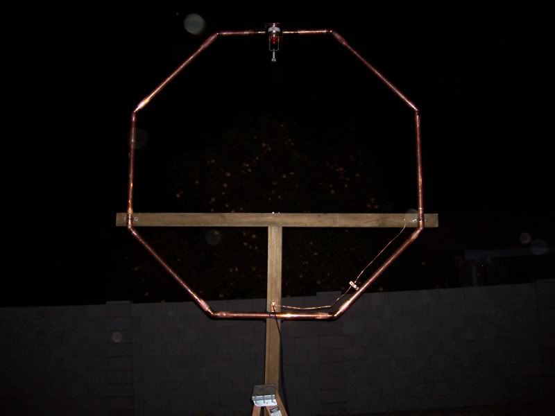
I posted pics of this antenna in an antenna thread a while back, but thought I'd go into more detail for those of you that want to give it a try. The octagon is only 6'3" in diameter with the lowest part of the loop at 7' above ground and it is equal in performance to my inverted V at 35 feet at the apex. The bandwidth is just under 10kz which is OK for me, but other hams have put motor drives on the variable capacitor with good results. It's a pretty pricey antenna to build, but it was a fun project and I still use it all of the time. Anyhow I hope somebody can use the info, it would make a good antenna for someone in an HOA, it can be mounted horizontally in an attic, or just set it right on the ground vertically polarized.
Once I decided to build a magnetic loop the first thing I needed was a suitable vacuum variable capacitor. I found the one below at Max Gain Systems on the Presidents page as a scratch & dent. It's rated at 5kv 100-1000pf but I have pushed it well beyond that voltage many times without issue. The mount was fabricated from sheet copper, a couple of lengths of small diameter copper pipe, and some reducers to mate it to the loop. I made the ghetto reduction drive assembly using a couple of stacks of standoffs. The reduction gear is 6:1. 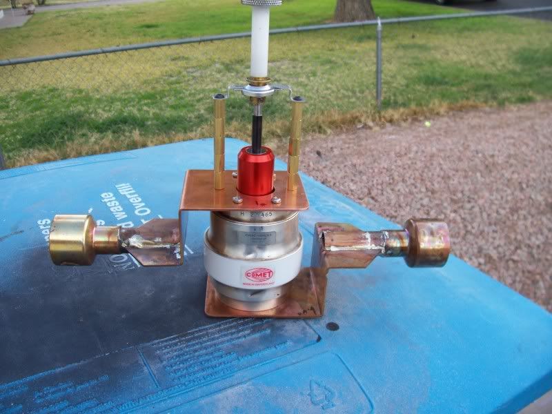
My friend and I put the main loop of the antenna together one afternoon. I used 1-5/8" copper pipe and 8 45 degree elbows. The pipes for 5 sides of the octagon were cut at 29", with the 6th/top side being cut to fit the capacitor. 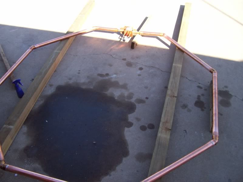
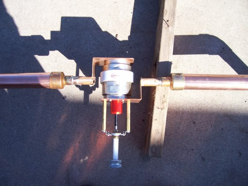
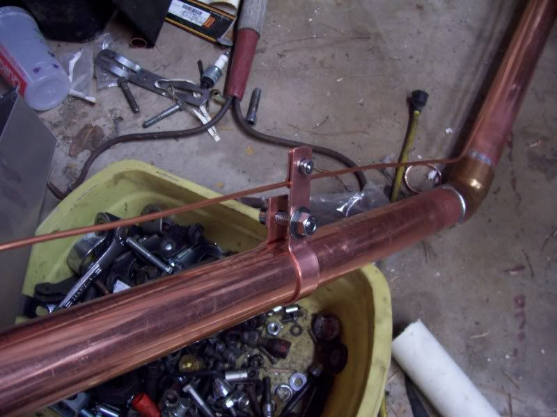
The feed is a simple gamma match. I took a 1" length of leftover scrap pipe, cut one side, hammered part of it flat and drilled the holes for the So-239 connector. This bracket was then soldered to the loop directly opposite the capacitor. The other end of the gamma match was made in a similar fashion but with a strip of copper sheet and stainless hardware. The loop should be tapped approx. 6" beyond the first elbow from the feedpoint. 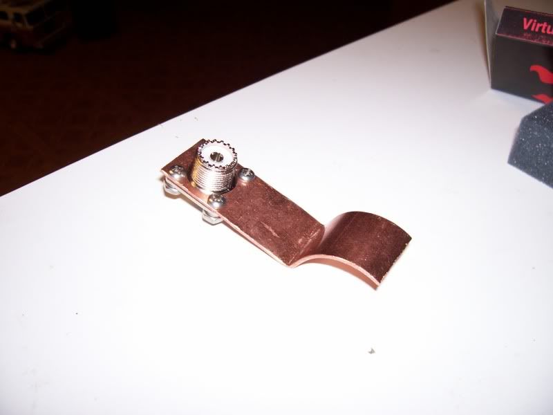
Here's a shot to give you an idea of how small it is for a 40m antenna. 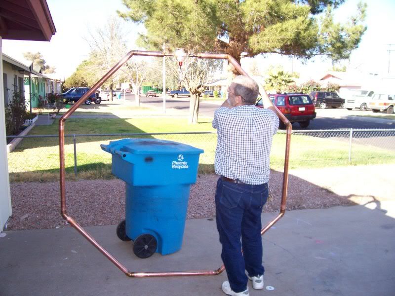
Below are couple of links I found interesting while researching this antenna. http://www.aa5tb.com/loop.html http://www.standpipe.com/w2bri/index.htm I've only found a few other hams that use these antennas, probably due to the high cost and the narrow bandwidth, I have mine parked on my favorite freq. (7.195mhz) and use my V for the rest of the band. Edit: Here's the specs on my version at 100 watts.. Loop Circumference 21.00 feet Conductor Diameter 1.63 inches Frequency 7.20 mHz Bandwidth 9.6 kHz Capacitor Value 95.1 pF Capacitor Voltage 3.9 kV Conductor Wavelength 0.162 lamda Efficiency 74.4 % Inductance 4.456 µH Inductive Reactance 201.6 ohms Loop Area 33.3 feet² Loop Diameter 6.3 feet Loop Q Value 746.3 Qres Radiation Resistance 0.101 ohms Resistance Loss 0.035 ohms I have a loop calculator program I found on the web that I can pass along to anyone that's interested. |
|
|
|
[#1]
Very cool .... Was looking at other antenna options Ill Has to do some more reading in that.
Just finished pricing parts ,,,, I think Ill pass on building this one ..... but very cool. |
|
|
|
[#2]
http://i98.photobucket.com/albums/l260/my65pan/000_0058.jpg
Obviously you spend more time building antennas than fixing your car––sorry, couldn't resist! |
|
|
|
[#3]
Quoted:
Very cool .... Was looking at other antenna options Ill Has to do some more reading in that. Just finished pricing parts ,,,, I think Ill pass on building this one ..... but very cool. Pretty pricey aren't they? You can always build a smaller one for a different band just for fun. Here's a picture of a 2m version I made using info from this site. http://users.tpg.com.au/users/ldbutler/VHFLoopAntenna.htm 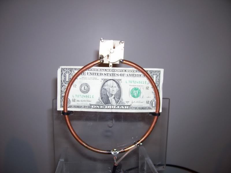
|
|
|
|
[#4]
Looks like BP's been in your garage. |
|
|
|
[#5]
Quoted:
http://i98.photobucket.com/albums/l260/my65pan/000_0058.jpg Looks like BP's been in your garage. My 41 year old pick-up marks that spot. |
|
|
|
[#6]
Quoted:
I have a loop calculator program I found on the web that I can pass along to anyone that's interested. Please |
|
|
|
[#7]
Quoted:
Quoted:
I have a loop calculator program I found on the web that I can pass along to anyone that's interested. Please Shoot me an IM so I can e-mail you the file. |
|
|
|
[#8]
This is the one I use for receiving loops. It seems to be pretty close. This is by Bruce Carter.
http://www.am-dx.com/loop_calc.htm Same one here: http://www.angelfire.com/mb/amandx/loop.html I cobbled one together like this once while my SWL antenna was down. I used a standard 9.6-365 pf tuning capacitor. The exact same tuning capacitor is also sold as 10-370 pf, 10-380 pf, and 10-400 pf. With the loop similar to the one in this link I was able to tune from 80 meters to 20 meters. http://www.am-dx.com/loop_calc.htm Some great loop antennas: http://makearadio.com/loops/index.php http://makearadio.com/loops/loops2.php and of course closely related... some really, really hip crystal radios! http://makearadio.com/crystal/index.php Video demo of effectiveness of tuned loop antenna. This one works via induction coupling it to the antenna built into the table radio. And I have had similar results with a loop I built similar to the one you see in this video. Mine is 24" on the diagonal (or 17" on each side), with 15 turns of 22 ga magnet wire, with 1/8" spacing between turns, using a standard 9.6-365 pf tuning cap. http://www.youtube.com/watch?v=l_keFgFYkO0 You might think of a tuned loop as a type of preselector, too. http://youtube.com/watch?v=QpGXECoY6zg http://youtube.com/watch?v=HXQeZxeCJ2c These are RECEIVING loops for the AM broadcast band. |
|
|
|
[#9]
Very cool,
I think it would be cheaper to melt my pennys... |
|
|
|
[#10]
|
|
|
|
[#11]
Here's a LINK to another transmitting loop design for 10m I haven't tried yet, but it's inexpensive and I have some hardline to give it a try. I ran it through the magnetic loop calculator program from the above post and the numbers don't look right though. 186.8 kHz bandwidth?
 Perhaps it isn't a true magnetic loop in this configuration...............? Perhaps it isn't a true magnetic loop in this configuration...............?
A_Free_Man, do you have any insight? The specs I came up with: Loop Circumference 10.00 feet Conductor Diameter 0.75 inches Frequency 28.50 mHz Bandwidth 186.8 kHz Capacitor Value 2.5 pF Capacitor Voltage 2.7 kV Conductor Wavelength 0.304 lamda Efficiency 88.5 % Inductance 2.720 µH Inductive Reactance 487.1 ohms Loop Area 8.0 feet² Loop Diameter 3.2 feet Loop Q Value 152.6 Qres Radiation Resistance 1.412 ohms Resistance Loss 0.184 ohms |
|
|
|
[#12]
What do you think of the MFJ loop tuners, my65pan?
|
|
|
|
[#13]
Quoted:
What do you think of the MFJ loop tuners, my65pan? I don't know, I'm not sure why you would need a different type of tuner for a loop. I have a nice roller inductor antenna coupler, but I try to make my antennas resonant so I don't need it. Do you have a link? Edit: I just looked at the reviews for the MFJ loop tuners, they are designed for wire loop antennas. Different animal. |
|
|
|
[#14]
The MFJ loop tuners aren't limited to wire, you can use copper tubing as well.
I'm thinking of building a square loop, 6 feet per side, that should tune nicely from the top of 30m to the bottom of 40m. The 1-5/8" copper tubing looks sweet! |
|
|
|
[#15]
Quoted:
Here's a LINK to another transmitting loop design for 10m I haven't tried yet, but it's inexpensive and I have some hardline to give it a try. I ran it through the magnetic loop calculator program from the above post and the numbers don't look right though. 186.8 kHz bandwidth? Perhaps it isn't a true magnetic loop in this configuration...............?
A_Free_Man, do you have any insight? The specs I came up with: Loop Circumference 10.00 feet Conductor Diameter 0.75 inches Frequency 28.50 mHz Bandwidth 186.8 kHz Capacitor Value 2.5 pF Capacitor Voltage 2.7 kV Conductor Wavelength 0.304 lamda Efficiency 88.5 % Inductance 2.720 µH Inductive Reactance 487.1 ohms Loop Area 8.0 feet² Loop Diameter 3.2 feet Loop Q Value 152.6 Qres Radiation Resistance 1.412 ohms Resistance Loss 0.184 ohms Not a clue. There's a guy, Chris Trask, that frequents the yahoo loop antenna group. He's done a lot of interesting research and building of SW loops. You might pose the question to him. http://groups.yahoo.com/group/loopantennas/ |
|
|
|
[#16]
Quoted:
Quoted:
Here's a LINK to another transmitting loop design for 10m I haven't tried yet, but it's inexpensive and I have some hardline to give it a try. I ran it through the magnetic loop calculator program from the above post and the numbers don't look right though. 186.8 kHz bandwidth? Perhaps it isn't a true magnetic loop in this configuration...............?
A_Free_Man, do you have any insight? The specs I came up with: Loop Circumference 10.00 feet Conductor Diameter 0.75 inches Frequency 28.50 mHz Bandwidth 186.8 kHz Capacitor Value 2.5 pF Capacitor Voltage 2.7 kV Conductor Wavelength 0.304 lamda Efficiency 88.5 % Inductance 2.720 µH Inductive Reactance 487.1 ohms Loop Area 8.0 feet² Loop Diameter 3.2 feet Loop Q Value 152.6 Qres Radiation Resistance 1.412 ohms Resistance Loss 0.184 ohms Not a clue. There's a guy, Chris Trask, that frequents the yahoo loop antenna group. He's done a lot of interesting research and building of SW loops. You might pose the question to him. http://groups.yahoo.com/group/loopantennas/ Thanks, I just signed up, lot's of interesting info! |
|
|
|
[#17]
Quoted:
Here's a LINK to another transmitting loop design for 10m I haven't tried yet, but it's inexpensive and I have some hardline to give it a try. I ran it through the magnetic loop calculator program from the above post and the numbers don't look right though. 186.8 kHz bandwidth? Perhaps it isn't a true magnetic loop in this configuration...............?
A_Free_Man, do you have any insight? The specs I came up with: Loop Circumference 10.00 feet Conductor Diameter 0.75 inches Frequency 28.50 mHz Bandwidth 186.8 kHz Capacitor Value 2.5 pF Capacitor Voltage 2.7 kV Conductor Wavelength 0.304 lamda Efficiency 88.5 % Inductance 2.720 µH Inductive Reactance 487.1 ohms Loop Area 8.0 feet² Loop Diameter 3.2 feet Loop Q Value 152.6 Qres Radiation Resistance 1.412 ohms Resistance Loss 0.184 ohms I'm not sure how I got the idea this was designed for 10m, my mistake. I punched in the wrong data etc. Disregard this info. |
|
|
 Win a FREE Membership!
Sign up for the ARFCOM weekly newsletter and be entered to win a free ARFCOM membership. One new winner* is announced every week!
You will receive an email every Friday morning featuring the latest chatter from the hottest topics, breaking news surrounding legislation, as well as exclusive deals only available to ARFCOM email subscribers.

AR15.COM is the world's largest firearm community and is a gathering place for firearm enthusiasts of all types.
From hunters and military members, to competition shooters and general firearm enthusiasts, we welcome anyone who values and respects the way of the firearm.

Subscribe to our monthly Newsletter to receive firearm news, product discounts from your favorite Industry Partners, and more.
Copyright © 1996-2024 AR15.COM LLC. All Rights Reserved.
Any use of this content without express written consent is prohibited.
AR15.Com reserves the right to overwrite or replace any affiliate, commercial, or monetizable links, posted by users, with our own.


